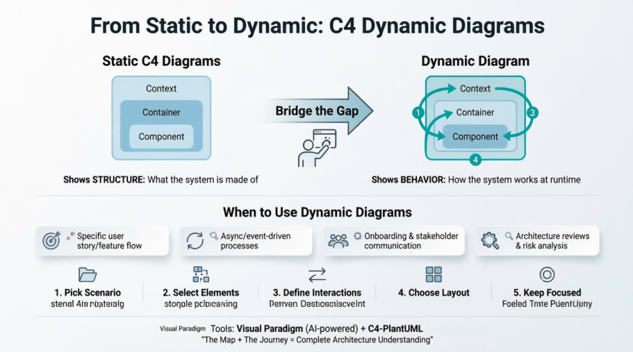
Software architecture documentation often faces a critical gap: we can beautifully map what a system is made of, but struggle to explain how it actually works when users interact with it. Static diagrams show structure—containers, components, and connections—but they leave readers wondering about the flow of data, the sequence of operations, and the runtime collaboration between elements.
Enter the C4 Dynamic Diagram. As one of the three supplementary diagrams in the C4 model (alongside System Landscape and Deployment diagrams), the Dynamic diagram bridges this gap by focusing on runtime behavior. It transforms abstract architecture into tangible narratives, showing how software systems, containers, or components collaborate over time to implement specific user stories, use cases, or business processes.
Whether you're onboarding new team members, conducting architecture reviews, or documenting complex event-driven flows, Dynamic diagrams provide the clarity that static models alone cannot. This comprehensive guide walks you through everything you need to know: what C4 Dynamic Diagrams are, why they matter, when to use them, how to create them, and practical examples using both Visual Paradigm and C4-PlantUML.
The C4 Dynamic Diagram is one of the three supplementary diagrams in the C4 model (alongside System Landscape and Deployment diagrams). While the core C4 diagrams (Context, Container, Component, Code) are static structure diagrams, the Dynamic diagram focuses on runtime behavior.
It is inspired by UML Communication Diagrams (numbered interactions with free-form layout) but can also be rendered in a more linear sequence-style format. This makes it excellent for explaining dynamic behavior without the full complexity of a pure UML Sequence Diagram.
The static C4 diagrams excel at showing what the architecture looks like (structure and relationships) but often leave readers wondering how it behaves at runtime.
Reasons to supplement:
In short: Static diagrams show the map; Dynamic diagrams show how traffic actually moves on the roads for a particular journey.
Use it when:
It is optional and should be created selectively — only for important or complex flows. Avoid creating one for every possible use case.
[Image placeholder: Decision flowchart showing "When to create a Dynamic Diagram" with criteria like complexity, stakeholder needs, and risk assessment]
Always include a diagram key/legend and link back to the relevant static C4 diagrams.
[Image placeholder: Annotated screenshot showing the 5-step creation process with visual callouts]
Visual Paradigm provides excellent first-class support for the full C4 model, including all six diagram types: System Context, Container, Component, System Landscape, Dynamic, and Deployment.
Key strengths (as of the December 2025 update and beyond):
This makes Visual Paradigm one of the most complete tools for end-to-end C4 modeling, especially when combining static structure with dynamic behavior and infrastructure views.
[Image placeholder: Visual Paradigm interface showing AI-generated C4 Dynamic Diagram with numbered interactions]
C4-PlantUML is the most popular way to generate C4 diagrams as code. For Dynamic diagrams, include C4_Dynamic.puml.
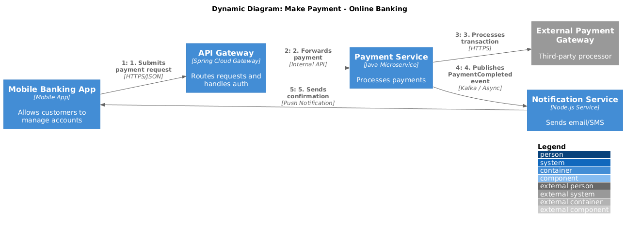
Example 1: Dynamic Diagram – Online Banking "Make Payment" Flow (Collaboration Style)
 @startuml
!include https://raw.githubusercontent.com/plantuml-stdlib/C4-PlantUML/master/C4_Dynamic.puml
' Optional: Horizontal layout often reads better for step-by-step flows
LAYOUT_LEFT_RIGHT()
LAYOUT_WITH_LEGEND()
title Dynamic Diagram: Make Payment - Online Banking
' 1. Define Elements
Container(customerMobileApp, "Mobile Banking App", "Mobile App", "Allows customers to manage accounts")
Container(apiGateway, "API Gateway", "Spring Cloud Gateway", "Routes requests and handles auth")
Container(paymentService, "Payment Service", "Java Microservice", "Processes payments")
Container(notificationService, "Notification Service", "Node.js Service", "Sends email/SMS")
System_Ext(paymentGateway, "External Payment Gateway", "Third-party processor")
' 2. Define Indexed Relationships
' Syntax: Rel(<from>, <to>, <label>, <technique>)
Rel(customerMobileApp, apiGateway, "1. Submits payment request", "HTTPS/JSON")
Rel(apiGateway, paymentService, "2. Forwards payment", "Internal API")
Rel(paymentService, paymentGateway, "3. Processes transaction", "HTTPS")
Rel(paymentService, notificationService, "4. Publishes PaymentCompleted event", "Kafka / Async")
Rel(notificationService, customerMobileApp, "5. Sends confirmation", "Push Notification")
@enduml
[Image placeholder: Rendered collaboration-style Dynamic diagram showing the payment flow with numbered arrows]
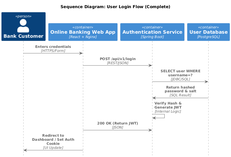
Example 2: Simpler Sequence-Style Dynamic Diagram (Login Flow)
@startuml
!include https://raw.githubusercontent.com/plantuml-stdlib/C4-PlantUML/master/C4_Sequence.puml
' Standard C4 styling for sequence diagrams
title Sequence Diagram: User Login Flow (Complete)
' 1. Define Participants
Person(user, "Bank Customer", "Wants to access account")
Container(webApp, "Online Banking Web App", "React + Nginx", "Customer UI")
Container(authService, "Authentication Service", "Spring Boot", "Identity Provider")
Container(userDatabase, "User Database", "PostgreSQL", "Credential Store")
' 2. The Flow
' Syntax: Rel(from, to, label, technique)
Rel(user, webApp, "Enters credentials", "HTTPS/Form")
Rel(webApp, authService, "POST /api/v1/login", "REST/JSON")
Rel(authService, userDatabase, "SELECT user WHERE username=?", "JDBC/SQL")
' Showing the return message from the DB
Rel(userDatabase, authService, "Return hashed password & salt", "SQL Result")
Rel(authService, authService, "Verify Hash & Generate JWT", "Internal Logic")
Rel(webApp, authService, "200 OK (Return JWT)", "JSON")
Rel(webApp, user, "Redirect to Dashboard / Set Auth Cookie", "UI Update")
@enduml
@startuml
!include https://raw.githubusercontent.com/plantuml-stdlib/C4-PlantUML/master/C4_Dynamic.puml
' Standard C4 Layout settings
LAYOUT_WITH_LEGEND()
' Left-to-right layout is often better for step-by-step dynamic flows
LAYOUT_LEFT_RIGHT()
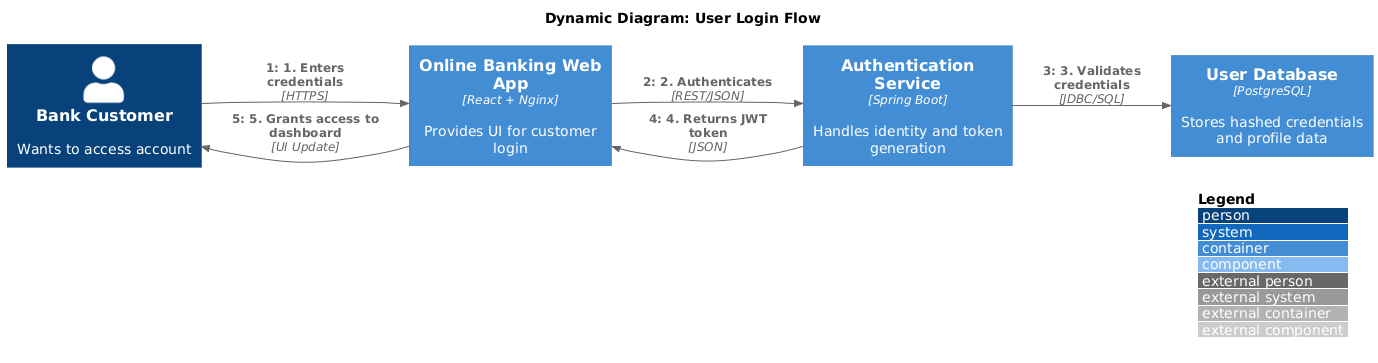
title Dynamic Diagram: User Login Flow
' 1. Define Elements
Person(user, "Bank Customer", "Wants to access account")
Container(webApp, "Online Banking Web App", "React + Nginx", "Provides UI for customer login")
Container(authService, "Authentication Service", "Spring Boot", "Handles identity and token generation")
Container(userDatabase, "User Database", "PostgreSQL", "Stores hashed credentials and profile data")
' 2. Define Dynamic Interactions
' Note: Numbering is included manually in the label for clarity
Rel(user, webApp, "1. Enters credentials", "HTTPS")
Rel(webApp, authService, "2. Authenticates", "REST/JSON")
Rel(authService, userDatabase, "3. Validates credentials", "JDBC/SQL")
Rel(authService, webApp, "4. Returns JWT token", "JSON")
Rel(webApp, user, "5. Grants access to dashboard", "UI Update")
@enduml
You can find more official samples (including message bus and Big Bank PLC examples) in the C4-PlantUML GitHub repository under the samples folder.
C4 Dynamic Diagrams are a powerful yet underutilized tool in the software architect's toolkit. By shifting focus from structure to behavior, they transform abstract architecture into actionable narratives that stakeholders can understand, developers can implement, and teams can validate.
Remember: Dynamic diagrams are optional and should be used selectively. Create them for complex, high-risk, or frequently misunderstood flows—not for every feature. When paired with static C4 diagrams, they provide a complete picture: the map and the journey.
Whether you choose Visual Paradigm's AI-powered generation for rapid prototyping or C4-PlantUML for code-based precision, the goal remains the same: communicate architecture clearly, reduce ambiguity, and align teams around how the system actually works. Start small, focus on one critical user story, and let your Dynamic diagram bring your architecture to life.
Mastering C4 Diagrams in Visual Paradigm: A Hands-On Review: Practical review comparing Visual Paradigm's four methods for creating C4 diagrams, with specific coverage of Dynamic diagram workflows.