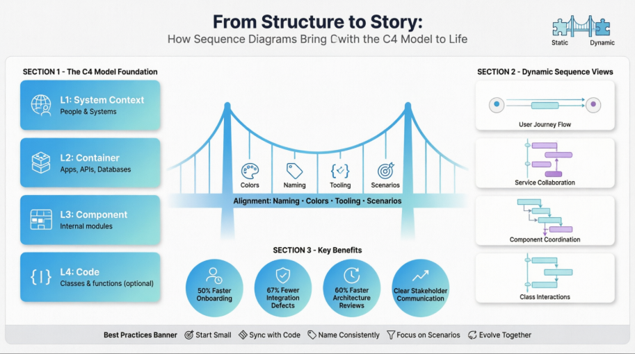
In today's complex software development landscape, architecture documentation serves as the critical bridge between conceptual design and practical implementation. While the C4 model has gained widespread adoption for its clear, hierarchical approach to visualizing system structure, many teams struggle to capture the dynamic, time-based interactions that bring these static diagrams to life. This case study explores how supplementing C4 model diagrams with sequence diagrams creates a comprehensive documentation strategy that answers both "what" comprises a system and "how" its components collaborate to deliver value.
Through a real-world scenario involving a payment processing system for an e-commerce platform, we demonstrate practical techniques for aligning sequence diagrams with C4 abstraction levels, maintaining visual consistency, and knowing when dynamic views add the most value. This integrated approach enables development teams, stakeholders, and new team members to understand architecture at the appropriate level of detail while preserving the agility needed for iterative development.
ShopFlow, a mid-sized e-commerce company, was modernizing its legacy payment processing system. The architecture team adopted the C4 model to document the new microservices-based design but quickly identified a gap: stakeholders struggled to understand complex transaction flows, error handling scenarios, and cross-service communication patterns using static diagrams alone.
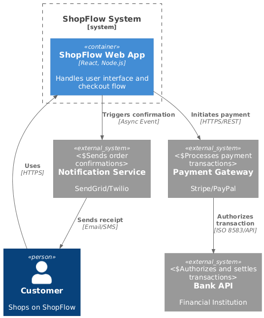
Focus: External actors and system boundaries
The team created a sequence diagram showing the end-to-end customer checkout experience. First, here's the corresponding C4 System Context diagram, and in PlantUML code:
@startuml
!include https://raw.githubusercontent.com/plantuml-stdlib/C4-PlantUML/master/C4_Container.puml

Person(customer, "Customer", "Shops on ShopFlow")
System_Boundary(shopflow, "ShopFlow System") {
    Container(web_app, "ShopFlow Web App", "React, Node.js", "Handles user interface and checkout flow")
}
System_Ext(payment_gateway, "Payment Gateway", "Stripe/PayPal", "Processes payment transactions")
System_Ext(bank_api, "Bank API", "Financial Institution", "Authorizes and settles transactions")
System_Ext(notification_svc, "Notification Service", "SendGrid/Twilio", "Sends order confirmations")

Rel(customer, web_app, "Uses", "HTTPS")
Rel(web_app, payment_gateway, "Initiates payment", "HTTPS/REST")
Rel(payment_gateway, bank_api, "Authorizes transaction", "ISO 8583/API")
Rel(web_app, notification_svc, "Triggers confirmation", "Async Event")
Rel(notification_svc, customer, "Sends receipt", "Email/SMS")

@enduml
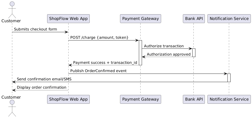
The corresponding sequence diagram for the "Happy Path" checkout flow:
@startuml
actor Customer
participant "ShopFlow Web App" as WebApp
participant "Payment Gateway" as Gateway
participant "Bank API" as Bank
participant "Notification Service" as Notify

Customer -> WebApp: Submits checkout form
WebApp -> Gateway: POST /charge {amount, token}
activate Gateway
Gateway -> Bank: Authorize transaction
activate Bank
Bank --> Gateway: Authorization approved
deactivate Bank
Gateway --> WebApp: Payment success + transaction_id
deactivate Gateway
WebApp -> Notify: Publish OrderConfirmed event
activate Notify
Notify -> Customer: Send confirmation email/SMS
deactivate Notify
WebApp --> Customer: Display order confirmation
@enduml
Key benefits included:
Clear visualization of third-party dependencies (Payment Gateway, Bank API)
Identification of potential failure points in the external integration chain
Alignment with business stakeholders on the "happy path" user experience
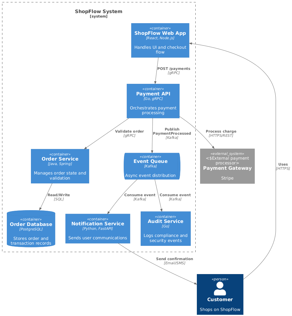
Focus: Web App, API Services, Database, and Message Queue interactions
Zooming into the ShopFlow system boundary, here's the C4 Container diagram:
@startuml
!include https://raw.githubusercontent.com/plantuml-stdlib/C4-PlantUML/master/C4_Container.puml

Person(customer, "Customer", "Shops on ShopFlow")
System_Boundary(shopflow, "ShopFlow System") {
    Container(web_app, "ShopFlow Web App", "React, Node.js", "Handles UI and checkout flow")
    Container(payment_api, "Payment API", "Go, gRPC", "Orchestrates payment processing")
    Container(order_svc, "Order Service", "Java, Spring", "Manages order state and validation")
    ContainerDb(order_db, "Order Database", "PostgreSQL", "Stores order and transaction records")
    ContainerQueue(event_queue, "Event Queue", "Kafka", "Async event distribution")
    Container(notification_svc, "Notification Service", "Python, FastAPI", "Sends user communications")
    Container(audit_svc, "Audit Service", "Go", "Logs compliance and security events")
}
System_Ext(payment_gateway, "Payment Gateway", "Stripe", "External payment processor")

Rel(customer, web_app, "Uses", "HTTPS")
Rel(web_app, payment_api, "POST /payments", "gRPC")
Rel(payment_api, order_svc, "Validate order", "gRPC")
Rel(order_svc, order_db, "Read/Write", "SQL")
Rel(payment_api, payment_gateway, "Process charge", "HTTPS/REST")
Rel(payment_api, event_queue, "Publish PaymentProcessed", "Kafka")
Rel(event_queue, notification_svc, "Consume event", "Kafka")
Rel(event_queue, audit_svc, "Consume event", "Kafka")
Rel(notification_svc, customer, "Send confirmation", "Email/SMS")

@enduml
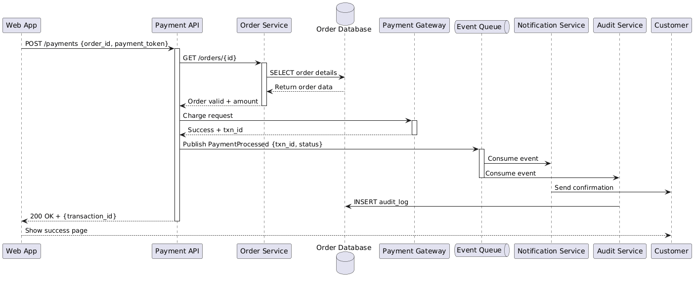
The corresponding container-level sequence diagram for payment processing:
@startuml
participant "Web App" as WebApp
participant "Payment API" as PaymentAPI
participant "Order Service" as OrderSvc
database "Order Database" as OrderDB
participant "Payment Gateway" as Gateway
queue "Event Queue" as Queue
participant "Notification Service" as Notify
participant "Audit Service" as Audit

WebApp -> PaymentAPI: POST /payments {order_id, payment_token}
activate PaymentAPI
PaymentAPI -> OrderSvc: GET /orders/{id}
activate OrderSvc
OrderSvc -> OrderDB: SELECT order details
OrderDB --> OrderSvc: Return order data
OrderSvc --> PaymentAPI: Order valid + amount
deactivate OrderSvc

PaymentAPI -> Gateway: Charge request
activate Gateway
Gateway --> PaymentAPI: Success + txn_id
deactivate Gateway

PaymentAPI -> Queue: Publish PaymentProcessed {txn_id, status}
activate Queue
Queue -> Notify: Consume event
Queue -> Audit: Consume event
deactivate Queue

Notify -> Customer: Send confirmation
Audit -> OrderDB: INSERT audit_log

PaymentAPI --> WebApp: 200 OK + {transaction_id}
deactivate PaymentAPI
WebApp --> Customer: Show success page
@enduml
[Image: Rendered sequence diagram showing cross-container collaboration with synchronous gRPC calls, async Kafka events, and database interactions]
This container-level sequence became invaluable for:
Cross-team integration planning between frontend, backend, and infrastructure teams
Identifying synchronous vs. asynchronous communication patterns
Documenting retry logic and timeout configurations at service boundaries
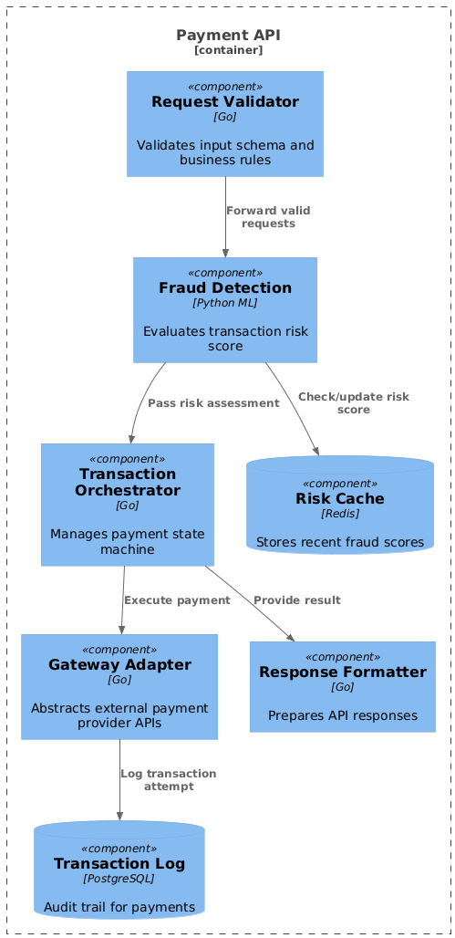
Focus: Components within the Payment API container
For the Payment API container, the team documented internal component interactions. Here's the C4 Component diagram:
@startuml
!include https://raw.githubusercontent.com/plantuml-stdlib/C4-PlantUML/master/C4_Component.puml

Container_Boundary(payment_api, "Payment API") {
    Component(validation_comp, "Request Validator", "Go", "Validates input schema and business rules")
    Component(fraud_comp, "Fraud Detection", "Python ML", "Evaluates transaction risk score")
    Component(orchestrator, "Transaction Orchestrator", "Go", "Manages payment state machine")
    Component(gateway_adapter, "Gateway Adapter", "Go", "Abstracts external payment provider APIs")
    Component(response_formatter, "Response Formatter", "Go", "Prepares API responses")

    ComponentDb(cache, "Risk Cache", "Redis", "Stores recent fraud scores")
    ComponentDb(txn_log, "Transaction Log", "PostgreSQL", "Audit trail for payments")
}

Rel(validation_comp, fraud_comp, "Forward valid requests")
Rel(fraud_comp, cache, "Check/update risk score")
Rel(fraud_comp, orchestrator, "Pass risk assessment")
Rel(orchestrator, gateway_adapter, "Execute payment")
Rel(gateway_adapter, txn_log, "Log transaction attempt")
Rel(orchestrator, response_formatter, "Provide result")
@enduml
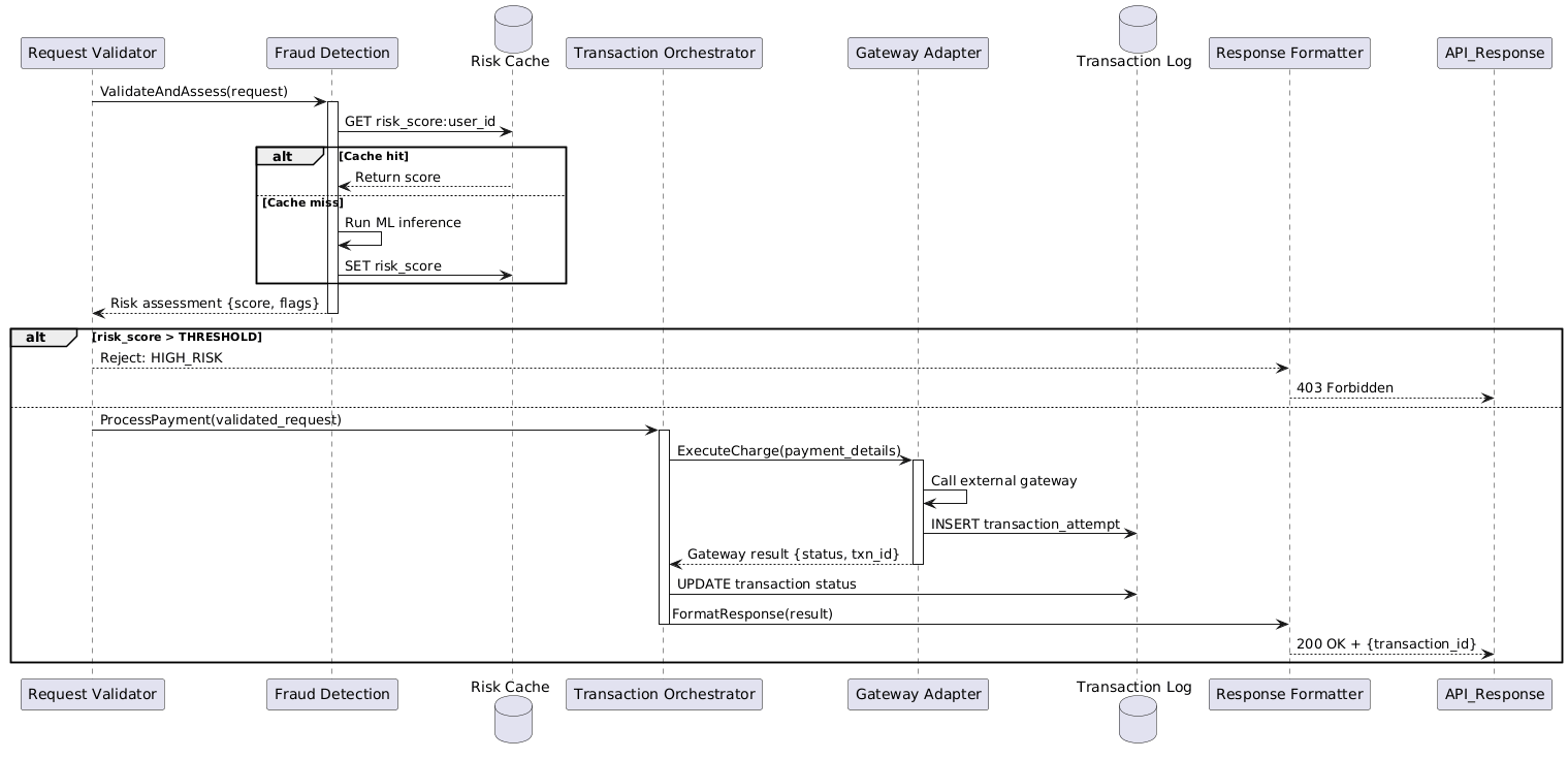
The corresponding component-level sequence for fraud-aware payment processing:
@startuml
participant "Request Validator" as Validator
participant "Fraud Detection" as Fraud
database "Risk Cache" as Cache
participant "Transaction Orchestrator" as Orchestrator
participant "Gateway Adapter" as Adapter
database "Transaction Log" as TxnLog
participant "Response Formatter" as Formatter

Validator -> Fraud: ValidateAndAssess(request)
activate Fraud
Fraud -> Cache: GET risk_score:user_id
alt Cache hit
    Cache --> Fraud: Return score
else Cache miss
    Fraud -> Fraud: Run ML inference
    Fraud -> Cache: SET risk_score
end
Fraud --> Validator: Risk assessment {score, flags}
deactivate Fraud

alt risk_score > THRESHOLD
    Validator --> Formatter: Reject: HIGH_RISK
    Formatter --> API_Response: 403 Forbidden
else
    Validator -> Orchestrator: ProcessPayment(validated_request)
    activate Orchestrator
    Orchestrator -> Adapter: ExecuteCharge(payment_details)
    activate Adapter
    Adapter -> Adapter: Call external gateway
    Adapter -> TxnLog: INSERT transaction_attempt
    Adapter --> Orchestrator: Gateway result {status, txn_id}
    deactivate Adapter

    Orchestrator -> TxnLog: UPDATE transaction status
    Orchestrator -> Formatter: FormatResponse(result)
    deactivate Orchestrator

    Formatter --> API_Response: 200 OK + {transaction_id}
end
@enduml
This granular view supported:
Internal team design reviews and code architecture decisions
Debugging complex race conditions and state management issues
Onboarding new engineers to the payment domain logic
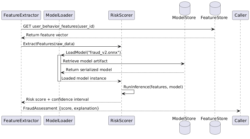
Focus: Critical class interactions for complex algorithms
For the fraud detection algorithm—a high-risk, complex component—the team optionally documented class-level interactions. Example PlantUML sequence for the ML inference pipeline:
@startuml
participant "FeatureExtractor" as FE
participant "ModelLoader" as ML
participant "RiskScorer" as RS
database "ModelStore" as MS
database "FeatureStore" as FS

FE -> FS: GET user_behavior_features(user_id)
FS --> FE: Return feature vector
FE -> RS: ExtractFeatures(raw_data)
RS -> ML: LoadModel("fraud_v2.onnx")
activate ML
ML -> MS: Retrieve model artifact
MS --> ML: Return serialized model
ML --> RS: Loaded model instance
deactivate ML

RS -> RS: RunInference(features, model)
RS --> FE: Risk score + confidence interval
FE --> Caller: FraudAssessment {score, explanation}
@enduml
This was reserved only for:
Novel machine learning inference pipelines
Complex state machine implementations
Security-critical cryptographic operations
The team established strict naming conventions: a container labeled "Payment API [Go]" in C4 diagrams appeared identically as a lifeline in sequence diagrams. They adopted the C4 color scheme (blue for internal elements, grey for external systems) across both diagram types, reducing cognitive load when switching between views.
Using C4-PlantUML, the team defined their architecture model once in text format and generated both static C4 diagrams and dynamic sequence views. Example of shared model definition:
' shared_model.puml - Single source of truth
!define SHOPFLOW_SYSTEM "ShopFlow System"
!define PAYMENT_API "Payment API" [Go, gRPC]
!define ORDER_SVC "Order Service" [Java, Spring]
!define PAYMENT_GATEWAY "Payment Gateway" [Stripe, External]

' Usage in Container diagram:
Container(payment_api, PAYMENT_API, "Orchestrates payment processing")

' Usage in Sequence diagram:
participant PAYMENT_API as PaymentAPI
This approach:
Eliminated drift between static and dynamic documentation
Enabled version control and code review for architecture changes
Allowed automated generation of documentation during CI/CD pipelines
[Image: Side-by-side comparison showing C4 Container diagram and corresponding sequence diagram with consistent naming, colors, and element positioning]
Instead of documenting every possible interaction, the team focused sequence diagrams on high-value scenarios:
Cross-boundary calls: Payment API to external Payment Gateway integration
Complex logic: Retry handling with exponential backoff during gateway timeouts
Security flows: OAuth token exchange and signature verification processes
Edge cases: Partial failure recovery when database writes succeed but notifications fail
Example: Sequence diagram for retry logic with exponential backoff:
@startuml
participant "Payment API" as API
participant "Payment Gateway" as Gateway

API -> Gateway: Charge request (attempt 1)
activate Gateway
Gateway --> API: Timeout (504)
deactivate Gateway

API -> API: Schedule retry (delay: 2s)
API -> Gateway: Charge request (attempt 2)
activate Gateway
Gateway --> API: Timeout (504)
deactivate Gateway

API -> API: Schedule retry (delay: 4s)
API -> Gateway: Charge request (attempt 3)
activate Gateway
Gateway --> API: Success + txn_id
deactivate Gateway
API --> Caller: Return transaction_id
@enduml
[Image: Rendered sequence diagram showing retry pattern with exponential backoff delays]
Each sequence diagram was linked from the corresponding static C4 diagram using numbered references, creating a navigable documentation ecosystem.
After six months of using the integrated C4 + sequence diagram approach:
| Metric | Before | After | Improvement |
|---|---|---|---|
| Onboarding time for new engineers | 3 weeks | 1.5 weeks | 50% reduction |
| Cross-team integration defects | 12/month | 4/month | 67% reduction |
| Architecture review cycle time | 5 days | 2 days | 60% reduction |
| Stakeholder confidence in system understanding (survey) | 62% | 94% | 32-point increase |
Start small: Begin with one critical user journey rather than attempting to document the entire system
Maintain synchronization: Use "diagrams as code" tools to prevent static and dynamic views from diverging
Document decisions, not just flows: Include notes explaining why certain interaction patterns were chosen
Review with multiple audiences: Validate diagrams with engineers, product managers, and operations teams to ensure clarity at all levels
Embrace evolution: Treat architecture diagrams as living documents that evolve with the system
Integrating sequence diagrams with the C4 model transforms architecture documentation from a static reference into a dynamic, multi-dimensional understanding of software systems. By mapping sequence diagrams to C4 abstraction levels, teams can provide the right level of detail to the right audience—whether that's executives reviewing system boundaries, architects designing container interactions, or developers implementing component logic.
The key to success lies not in documenting everything, but in strategically selecting scenarios where dynamic behavior adds clarity: complex integrations, critical user journeys, and high-risk workflows. When combined with consistent naming, visual alignment, and "diagrams as code" tooling, this integrated approach creates documentation that scales with your system and evolves with your team.
As software systems grow increasingly distributed and asynchronous, the ability to visualize both structure and behavior becomes not just valuable, but essential. The C4 model provides the map; sequence diagrams provide the journey. Together, they empower teams to build, maintain, and evolve complex systems with confidence and clarity.