
For decades, software modeling meant staring at a blank canvas, manually dragging and dropping boxes, and drawing endless arrows. While Unified Modeling Language (UML) remains the gold standard for visualizing software architecture, the traditional process is often slow, prone to human error, and quickly becomes outdated the moment the code changes.
Enter the modern "Power Trio" of software design: UML Modeling, Artificial Intelligence (AI), and Diagram-as-Code.
When used in isolation, these tools are helpful. But when unified, they transform software design from a tedious chore into a rapid, automated, and highly accurate process. Visual Paradigm (VP) is an enterprise-grade platform that brings this trio together under one roof.
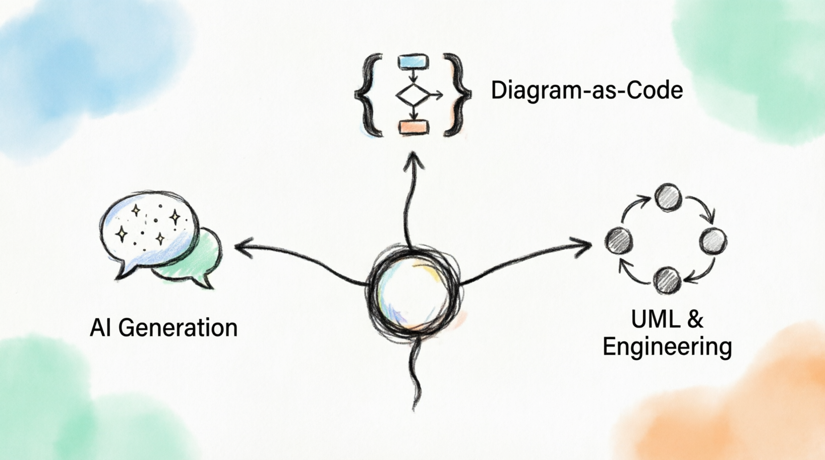
In this comprehensive, beginner-friendly tutorial, we will walk through how to leverage Visual Paradigm as your central hub. You will learn how to use the AI Chatbot to generate diagrams from plain English, refine them using PlantUML (Diagram-as-Code), validate your models, and perform round-trip engineering to keep your diagrams and code perfectly in sync.
Let’s turn your ideas into production-ready deliverables with minimal manual effort.
Before we begin, ensure you have the following:
Visual Paradigm: Download and install Visual Paradigm (the Community Edition or a free trial of the Professional Edition will work for this tutorial).
AI Features: Ensure your VP installation has the AI Assistant enabled (usually found in the right-hand panel or via the Tools > AI menu).
Basic Knowledge: A fundamental understanding of what a Class Diagram or Use Case Diagram is. No advanced coding skills are required!
The biggest hurdle in UML is starting from scratch. Visual Paradigm’s AI Chatbot eliminates this by allowing you to describe your system in plain English and instantly generating the corresponding UML diagram.
Imagine you are tasked with designing a Smart Library Management System. You need a Class Diagram showing the core entities and their relationships.
Open Visual Paradigm and create a new Class Diagram.
Open the AI Assistant panel (usually on the right side of the screen).
Type the following prompt into the chat:
"Create a class diagram for a library system. Include classes for Book, Member, and Loan. A Member can borrow multiple Books through a Loan. A Book has a title, ISBN, and availability status. A Member has a name and membership ID. Include a method in the Loan class to calculate overdue fines."Press Enter and wait a few seconds.
The AI will instantly populate your canvas with a fully structured Class Diagram, complete with attributes, methods, and correct multiplicity (e.g., 1 to 0..*).
To understand what the AI just built under the hood, here is the equivalent PlantUML representation of the generated structure:
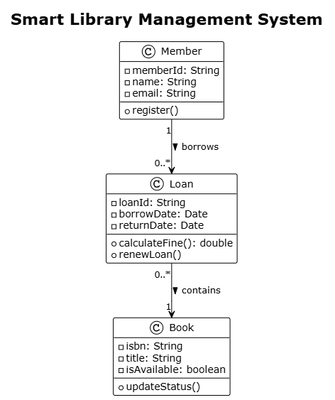
@startuml
!theme plain
title Smart Library Management System

class Book {
    - isbn: String
    - title: String
    - isAvailable: boolean
    + updateStatus()
}

class Member {
    - memberId: String
    - name: String
    - email: String
    + register()
}

class Loan {
    - loanId: String
    - borrowDate: Date
    - returnDate: Date
    + calculateFine(): double
    + renewLoan()
}

Member "1" --> "0..*" Loan : borrows >
Loan "0..*" --> "1" Book : contains >

@enduml
Note: While VP generates this visually, understanding the PlantUML syntax helps when we move to Step 2.
Visual diagrams are great for presentations, but they are terrible for version control (like Git). This is where Diagram-as-Code comes in. Visual Paradigm natively supports PlantUML, allowing you to write, edit, and version-control your diagrams as text files.
Let’s say the stakeholders just requested a new feature: we need to track Fines and link them to the Member who has to pay them. Instead of manually drawing new boxes, we will use code.
In Visual Paradigm, go to Tools > PlantUML > Edit PlantUML (or right-click the diagram background and select the PlantUML option).
A text editor will open, showing the underlying code of your current diagram.
Add the following code at the bottom of the editor to introduce the Fine class:
class Fine {
    - fineId: String
    - amount: double
    - isPaid: boolean
    + payFine()
}

Member "1" --> "0..*" Fine : incurs >
Loan "1" --> "0..1" Fine : generates >
Click OK or Sync.
Visual Paradigm instantly parses the new text and visually updates your diagram, drawing the new Fine class and the relationship arrows perfectly aligned with your existing layout. You now have a diagram that can be saved as a .puml text file and tracked in Git!
A common beginner mistake is creating diagrams that violate UML rules (e.g., connecting a Class to a Use Case, or forgetting to define the multiplicity of a relationship). Visual Paradigm acts as your strict but helpful mentor.
Let’s intentionally make a mistake. In the diagram, draw an association line directly from the Book class to the calculateFine() method inside the Loan class. (In UML, classes connect to classes; methods don't have direct relationship lines).
Go to Diagram > Validate Diagram (or click the "Check Diagram" icon in the toolbar).
The Diagram Validator panel will open at the bottom.
VP will highlight the invalid line in red and display a clear error message: "Invalid relationship: Association cannot connect a Class to an Operation."
Simply delete the line, run the validator again, and watch the green checkmark appear. Your model is now structurally sound and adheres to strict UML standards.
This is where Visual Paradigm truly shines as an enterprise tool. Round-trip engineering ensures that your diagrams and your actual source code never drift apart.
Go to Code > Generate Code (or right-click the project in the project browser and select Generate Code).
Select Java as your target language.
VP will generate clean, well-commented Java classes (Book.java, Member.java, Loan.java, Fine.java) complete with getters, setters, and the relationships mapped as object references.
Now, imagine your development team is working on the code. A developer opens Loan.java and adds a new method: public void sendOverdueEmail().
Instead of manually updating the UML diagram, go to Code > Sync Diagram with Code (or Reverse Engineer).
Select the updated Java files.
Visual Paradigm will read the modified Java code and automatically add the sendOverdueEmail() method to the Loan class box in your visual diagram.
Your visual model and your source code are now 100% synchronized, with zero manual redrawing required.
Software isn't built in a vacuum. You need to share your work with stakeholders, project managers, and other developers.
For Non-Technical Stakeholders: Use the Export feature to save your diagram as a high-resolution PNG, PDF, or SVG. You can also use VP’s Web Publisher to share a read-only, interactive web link of your diagram.
For the Development Team: Use VP’s built-in Comment and Review tools. Team members can leave sticky notes directly on specific classes or relationships in the diagram, fostering asynchronous collaboration without needing a separate meeting.
Visual Paradigm is much more than just a digital whiteboard for drawing boxes and arrows. By unifying UML, AI, and Diagram-as-Code, it fundamentally changes how you approach software design.
Let's recap the powerful workflow you've just learned:
Ideate: Use the AI Chatbot to instantly generate a baseline UML diagram from plain English.
Refine: Use PlantUML (Diagram-as-Code) to make rapid, version-controllable adjustments to your models.
Validate: Use the built-in Validator to ensure your architecture strictly adheres to UML standards.
Implement: Use Round-Trip Engineering to generate production-ready code, and keep your diagrams automatically synced as the code evolves.
By leveraging Visual Paradigm as your central hub, you eliminate the tedious manual labor of software modeling. You spend less time drawing lines and more time designing brilliant, robust software architectures.
Your Next Step: Open Visual Paradigm, fire up the AI Chatbot, and try modeling a system you are passionate about—whether it's a video game inventory system, a social media app, or a smart home controller. Experience the power of the modern modeling trio for yourself!

