
In software engineering, one of the most critical challenges is bridging the gap between high-level business requirements and low-level technical implementation. The Unified Modeling Language (UML) provides a robust framework to solve this problem. While Use Cases define what a system must do from the user's perspective, they do not explain how the system achieves it.
To cross this bridge, UML utilizes Collaborations and Interactions. This guide explores how these conceptual building blocks work together to translate functional requirements into actionable, dynamic system behaviors, ensuring that the final implementation faithfully delivers on the original business vision.
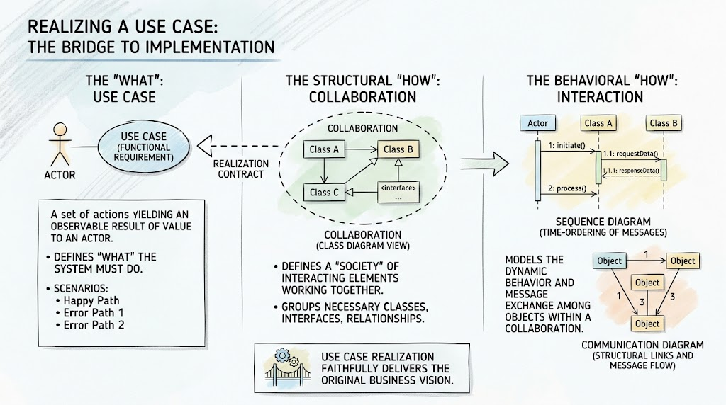
Before diving into the mechanics of use case realization, it is essential to understand the core terminology:
The process of realizing a use case is divided into two primary dimensions: structural and behavioral.
A collaboration is the primary mechanism for realizing a use case. It identifies the specific "society" of classes, interfaces, and other structural elements required to carry out the use case.
While the collaboration identifies who is participating, the interaction defines what they do and how they communicate.
The connection binding the requirement to the implementation is the realization relationship.
To illustrate these concepts, let's model the "Process Online Payment" use case for an e-commerce system.
This diagram shows the high-level requirement (the Use Case) and the Collaboration that realizes it, connected by the standard UML realization notation.
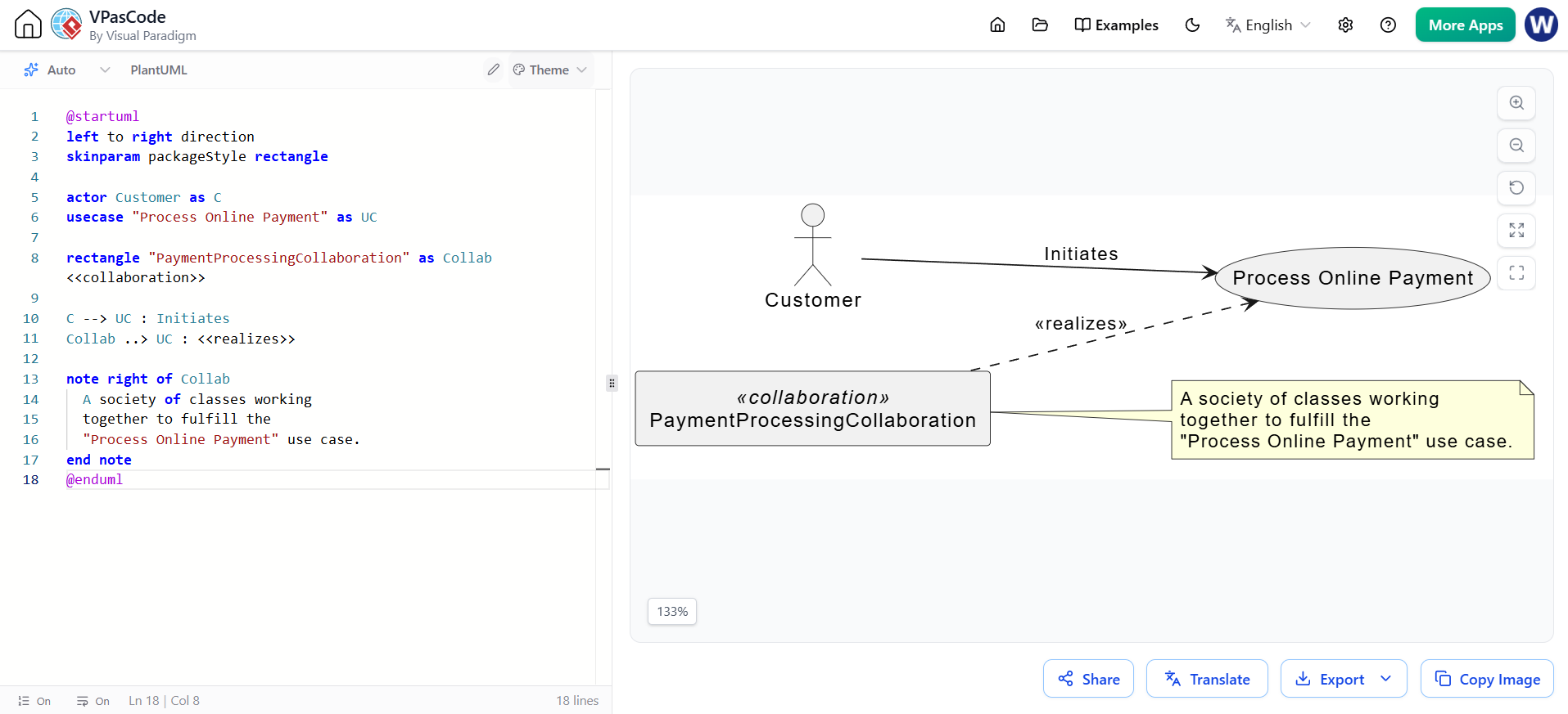
@startuml
left to right direction
skinparam packageStyle rectangle

actor Customer as C
usecase "Process Online Payment" as UC

rectangle "PaymentProcessingCollaboration" as Collab <<collaboration>>

C --> UC : Initiates
Collab ..> UC : <<realizes>>

note right of Collab
  A society of classes working
  together to fulfill the
  "Process Online Payment" use case.
end note
@enduml
This Class Diagram illustrates the "society" of classes identified by the collaboration. It shows the static structure and the relationships between the objects that will participate in the interaction.
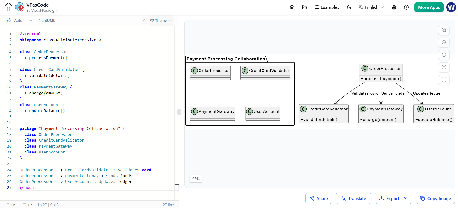
@startuml
skinparam classAttributeIconSize 0

class OrderProcessor {
  + processPayment()
}
class CreditCardValidator {
  + validate(details)
}
class PaymentGateway {
  + charge(amount)
}
class UserAccount {
  + updateBalance()
}

package "Payment Processing Collaboration" {
  class OrderProcessor
  class CreditCardValidator
  class PaymentGateway
  class UserAccount
}

OrderProcessor --> CreditCardValidator : Validates card
OrderProcessor --> PaymentGateway : Sends funds
OrderProcessor --> UserAccount : Updates ledger
@endumlThis Sequence Diagram models a specific scenario (the "Happy Path" for a successful payment). It shows the dynamic flow of control and message exchange among the objects defined in the collaboration.
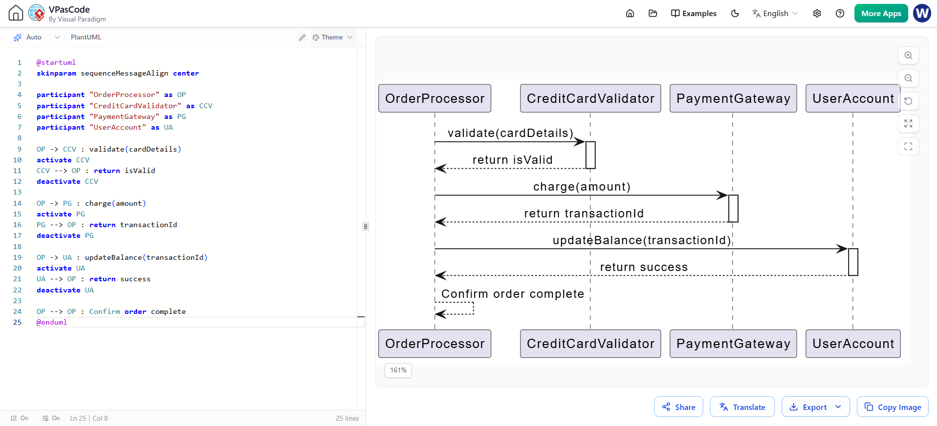
@startuml
skinparam sequenceMessageAlign center

participant "OrderProcessor" as OP
participant "CreditCardValidator" as CCV
participant "PaymentGateway" as PG
participant "UserAccount" as UA

OP -> CCV : validate(cardDetails)
activate CCV
CCV --> OP : return isValid
deactivate CCV

OP -> PG : charge(amount)
activate PG
PG --> OP : return transactionId
deactivate PG

OP -> UA : updateBalance(transactionId)
activate UA
UA --> OP : return success
deactivate UA

OP --> OP : Confirm order complete
@enduml
Translating business requirements into software architecture requires more than just listing features; it requires a structured methodology to define system behavior. By leveraging UML's Collaborations and Interactions, software architects and developers can seamlessly bridge the gap between the "what" and the "how."
Collaborations provide the necessary structural blueprint, identifying the society of objects required for the task. Interactions provide the behavioral storyboard, detailing the exact message flows and control sequences. Bound together by the realization relationship, this approach ensures that every line of code written is directly traceable to a specific business requirement, resulting in systems that are robust, well-documented, and perfectly aligned with user needs.

