The class diagram is the most widely used UML tool for modeling the static structure of a system. It defines the system's elements and their relationships, which remain valid over time even as specific data changes. Used throughout the software development process, it serves as a conceptual vocabulary in early phases and a blueprint for implementation or automatic code generation in later stages. To understand class diagrams, one must first recognize objects—identifiable individuals in a system—and their relationships, known as links.
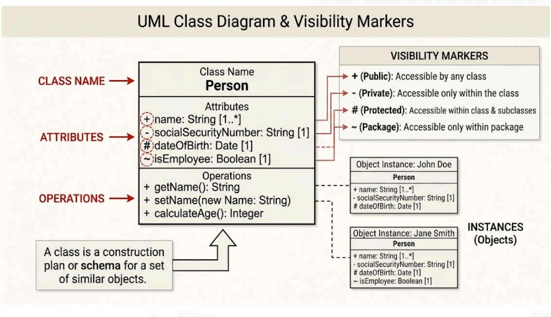
A class is a construction plan or schema for a set of similar objects, known as its instances.
Notation: Represented as a rectangle with up to three compartments: the Class Name, Attributes, and Operations.
Attributes: Describe the structural characteristics of the class. Syntax includes visibility, name, type, and multiplicity (e.g., + name: String).
Operations: Define the behavior or services an object provides. Syntax includes visibility, name, parameters, and return type.
Visibility Markers: These define access levels: + (public), - (private), # (protected), and ~ (package).
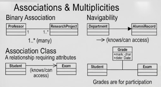
Associations model the potential communication paths between class instances.
Multiplicities: Indicate how many objects of one class can be linked to a single object of the partner class (e.g., 0..1, 1, or * for many).
Navigability: An arrowhead indicates that an object "knows" its partner and can access its visible features.
Association Classes: Used when a relationship itself requires its own attributes or operations (e.g., a "Grade" assigned to the relationship between a "Student" and an "Exam").
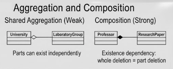
These are specialized "part-whole" relationships.
Shared Aggregation (Hollow Diamond): Represents a weak belonging; parts can exist independently of the whole.
Composition (Solid Diamond): Represents a strong existence dependency; if the whole is deleted, the parts are also deleted.
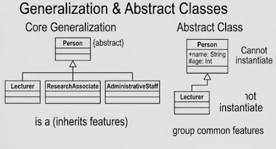
Also called inheritance, this represents an "is a" relationship where a subclass inherits all visible attributes, operations, and associations from a superclass.
Abstract Classes: Labeled with {abstract} or written in italics, these classes cannot be instantiated and exist only to group common features for subclasses.
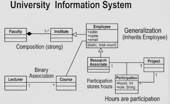
Identifying Classes: From a requirement for a university, we identify nouns like Faculty, Institute, Employee, Research Associate, and Course.
Attributes: For Employee, we add ssNo, name, and email. We might add a class variable (static attribute) like counter to track the total number of employees.
Relationships:
A Generalization shows that Research Associate is a type of Employee.
A Composition indicates that a Faculty consists of multiple Institutes (the institutes cannot exist without the faculty).
A Binary Association links a Lecturer to the Courses they teach.
An Association Class called Participation stores the hours a Research Associate spends on a specific Project.
Practice Abstraction: To keep diagrams clear, only include details relevant to the current development phase; avoid an "unnecessary flood of information".
Naming Conventions: Class names should be singular nouns starting with an uppercase letter, while attributes and operations should start with a lowercase letter.
Identify Derived Attributes: Use a forward slash (/) for attributes that can be calculated from others, such as /age derived from a date of birth.
Nouns vs. Verbs: When analyzing requirements, nouns typically indicate potential classes, while verbs often result in operations.
Identity vs. Value: Remember that objects have a unique identity even if their attributes are identical, whereas Data Types (like Integer or String) are defined only by their values.
The class diagram is an indispensable foundation for object-oriented modeling, providing a rigorous yet flexible way to describe system structure. By standardizing how we represent data, behavior, and complex relationships like composition and inheritance, it bridges the gap between high-level requirements and executable code. When used in conjunction with other UML diagrams, it ensures the model is consistent and errors are caught early in the development lifecycle.