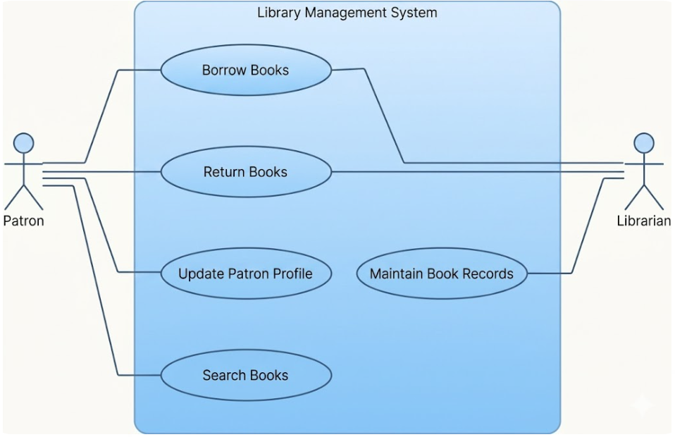
The use case diagram is a fundamental tool in object-oriented modeling used to describe the functional requirements of a system from a user’s perspective. It focuses on what a system should do rather than how it is implemented, abstracting away details like data structures and algorithms. By answering questions regarding what is being described (the system), who interacts with it (the actors), and what those actors can do (the use cases), the diagram establishes a clear communication bridge between customers and developers.
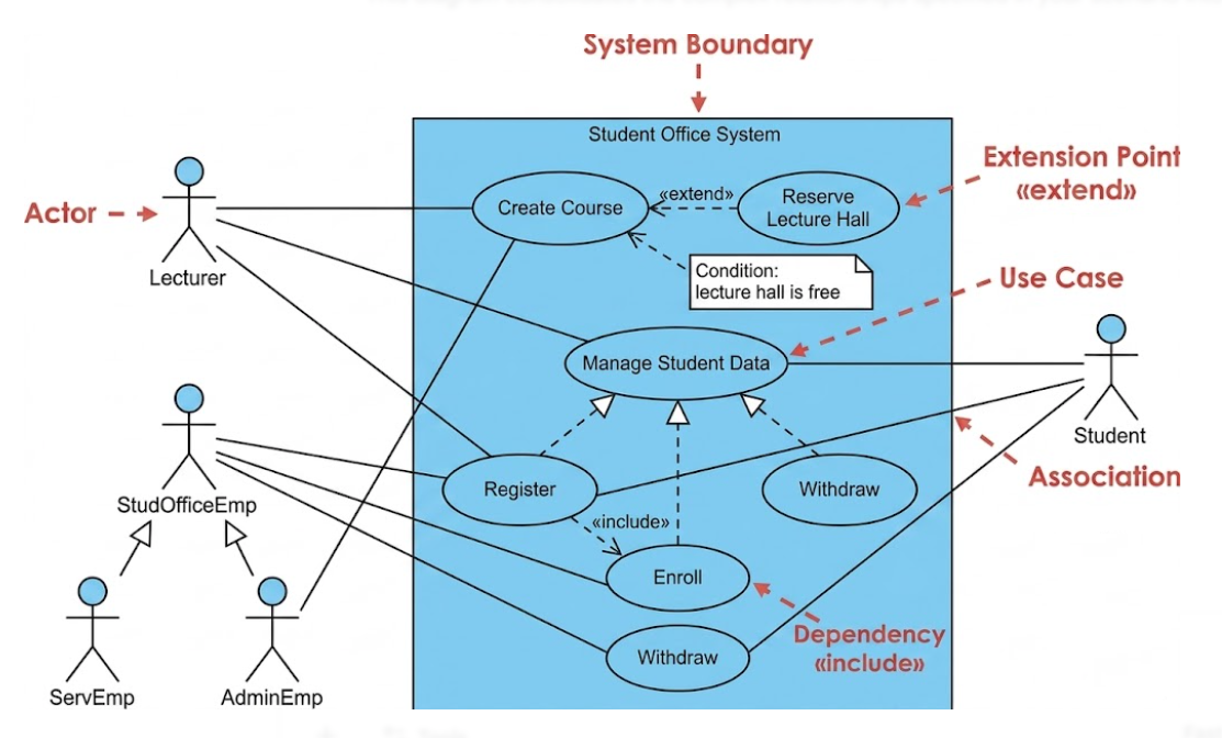
The System Boundary: Represented by a rectangle, the system boundary clarifies what is part of the software and what is external to it.
Use Cases: These are units of functionality, typically drawn as ellipses, that provide a tangible benefit to one or more actors. They are often triggered by an actor or a specific event.
Actors: Represented by stick figures or rectangles labeled with «actor», actors are roles that users (human or non-human) adopt when interacting with the system. Actors always reside outside the system boundaries.
Associations: These are solid lines connecting actors to use cases, indicating that the actor participates in the execution of that specific functionality. Multiplicities may be added to show how many instances of an actor or use case are involved.
Actor Generalization: Similar to inheritance in programming, a sub-actor inherits all associations from a super-actor, representing an “is a” relationship.
«include» Relationship: This is used when one use case requires the functionality of another to be complete. The arrow points from the base use case to the included one.
«extend» Relationship: This represents optional behavior that may be added to a base use case under specific conditions. It often utilizes extension points to define exactly where the behavior is inserted.
Use Case Generalization: This allows common behaviors to be grouped into a parent use case, which child use cases then inherit and potentially refine.
In a university’s student office system, the actors might include a Lecturer, a Student, and two types of employees: Service Employees (ServEmp) and Administration Employees (AdminEmp). To simplify, both employee types inherit from a general StudOfficeEmp actor.
The use cases involve functions like Register, Enroll, and Withdraw, which can be grouped under an abstract parent use case called Manage student data. Because matriculation always involves enrollment, the Register use case would include the Enroll use case. Additionally, the Create course use case might be extended by Reserve lecture hall, but only if the condition “lecture hall is free” is met.
To create effective and accurate diagrams, keep these best practices in mind:
Avoid Modeling Processes: Use case diagrams are not flowcharts; do not use «include» or «extend» to show a chronological sequence of steps.
Set Correct Boundaries: Ensure actors are truly external; if a user is part of the system’s internal implementation, they should not be modeled as an actor.
Maintain Abstraction Levels: Do not mix high-level business goals (e.g., Manage student data) with low-level technical features (e.g., Select printer) in the same diagram.
Don’t Over-Decompose: Avoid “functional decomposition” where every sub-step (like “Log in” or “Enter data”) is modeled as a separate use case; these details belong in the use case description.
Consolidate Redundancy: Instead of separate use cases for “Create,” “Update,” and “Delete,” group them into a single “Manage” use case to keep the diagram manageable.
While the use case diagram appears simple due to its limited set of graphical elements, it is an indispensable tool for requirements analysis. It ensures that no critical functionality is forgotten and that the system’s goals align with customer expectations. By focusing on the roles of users and the high-level benefits the system provides, it serves as the blueprint for more detailed technical modeling in subsequent phases of development.