The use case diagram serves as a vital communication bridge between customers and developers, ensuring that requirements are understood before technical design begins. It provides a high-level view of a system's functionality, focusing entirely on what the system should do rather than how it will be implemented. By abstracting away complex details like data structures and algorithms, the diagram allows stakeholders to focus on the tangible benefits provided to the user.
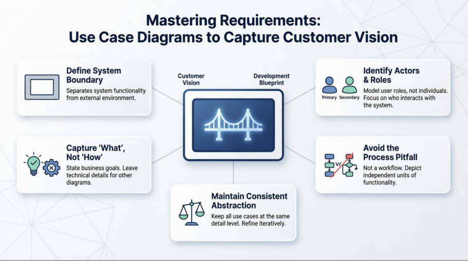
A critical first step in capturing a customer's vision is defining the system boundary, represented by a rectangle. This boundary clarifies what functionality is part of the software and what resides in the external environment. Elements inside the boundary are the use cases—the units of functionality the system provides. Elements outside the boundary are actors, representing the roles that human users or external systems play when interacting with the software.
To identify the correct actors, modelers must ask who uses the main functions, who requires support for daily work, and which external systems must communicate with the software. It is important to note that actors are not specific individuals but roles; for example, one person might act as both a "Student" and a "Tutor" at different times.
Primary Actors: These are the users who derive a direct benefit from a use case.
Secondary Actors: These provide the necessary functionality for a use case to execute but do not receive the primary benefit, such as an external E-Mail Server.
A common mistake in requirement gathering is getting lost in implementation details. Use cases should represent customer requirements at a high level of abstraction. For instance, a use case titled "Query student data" is appropriate because it describes a goal, whereas "Open SQL Connection" is an implementation detail that belongs in other diagrams, such as the class diagram.
One of the most frequent errors is modeling processes or workflows within a use case diagram. While it is tempting to use «include» or «extend» relationships to show a chronological sequence of steps, this is an incorrect use of the diagram. Use case diagrams are not flowcharts; they should depict independent units of functionality that provide a benefit. Chronological details and specific procedural steps should instead be documented in the use case description or an activity diagram.
To capture a clear vision, all use cases in a single diagram must remain on the same abstraction level. Mixing high-level business objectives, like "Manage student data," with low-level technical features, like "Select printer," creates confusion. Modelers should proceed iteratively: first identifying top-level business goals and then refining them into technical requirements in subsequent versions of the model.
When used correctly, the use case diagram is a powerful tool for requirements analysis that prevents the serious consequences of forgotten or imprecise specifications. By clearly defining boundaries, identifying roles, and avoiding the trap of functional decomposition, developers can create a blueprint that truly reflects the customer’s expectations. This foundation ensures that the final system is not only technically sound but also successful in meeting user needs.