In the realm of software engineering, complexity is the silent adversary. As systems grow in scale and sophistication, the human intellect struggles to comprehend the totality of their structure, behavior, and deployment. A single diagram or model, no matter how detailed, is insufficient to capture the multifaceted nature of a nontrivial software-intensive system.
To navigate this complexity, architects rely on a 360-degree look through several complementary and interlocking views. This approach, rooted in the Unified Modeling Language (UML), posits that architecture represents the set of significant decisions about the organization, selection of structural elements, their behavior, and their composition into larger subsystems. By projecting the system into five distinct but interconnected views—Use Case, Design, Process, Implementation, and Deployment—we can manage complexity, mitigate technical risks, and ensure that all stakeholder concerns are addressed.
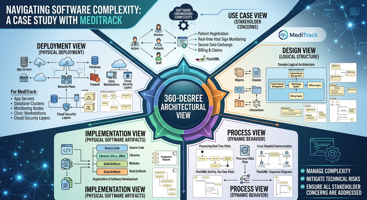
This case study explores these five views using a realistic example: "MediTrack," a hypothetical distributed healthcare management system. MediTrack handles patient records, real-time vital sign monitoring, billing, and secure data exchange between hospitals and clinics. Through this lens, we will demonstrate how each view contributes to a holistic architectural understanding, supported by PlantUML diagrams for practical application.
The Use Case View is the entry point for understanding the system from the perspective of its end users, analysts, and testers. It does not delve into internal mechanics but rather specifies the forces that shape the architecture by defining what the system must do to provide value.
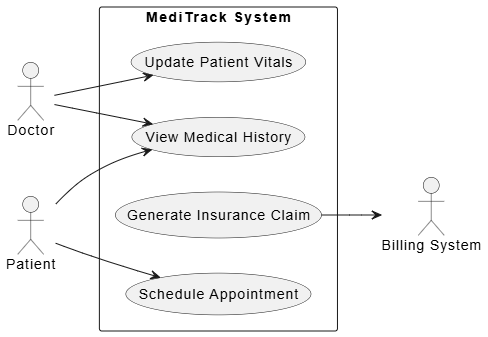
PlantUML Use Case View Example
@startuml
left to right direction
actor "Doctor" as Doctor
actor "Patient" as Patient
actor "Billing System" as Billing

rectangle "MediTrack System" {
  usecase "Update Patient Vitals" as UC1
  usecase "View Medical History" as UC2
  usecase "Generate Insurance Claim" as UC3
  usecase "Schedule Appointment" as UC4
}

Doctor --> UC1
Doctor --> UC2
Patient --> UC4
Patient --> UC2
UC3 --> Billing
@enduml
Tip: Use the Use Case View to align stakeholders early. It ensures that the architecture is driven by user needs rather than technological preferences.
The Design View encompasses the classes, interfaces, and collaborations that form the vocabulary of the problem and its solution. It primarily supports the functional requirements—the services the system provides to end users.
PatientRecord: Contains attributes like patientID, medicalHistory, and allergies.VitalSign: Represents real-time data points such as heartRate and bloodPressure.IMedicalDataService: Defines operations like getRecord() and updateVitals(), hiding the underlying database complexity.AppointmentScheduler collaborates with CalendarService and NotificationEngine to send reminders.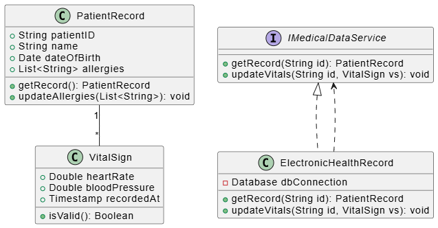
PlantUML Design View Example
@startuml
class PatientRecord {
  +String patientID
  +String name
  +Date dateOfBirth
  +List<String> allergies
  +getRecord(): PatientRecord
  +updateAllergies(List<String>): void
}

class VitalSign {
  +Double heartRate
  +Double bloodPressure
  +Timestamp recordedAt
  +isValid(): Boolean
}

interface IMedicalDataService {
  +getRecord(String id): PatientRecord
  +updateVitals(String id, VitalSign vs): void
}

class ElectronicHealthRecord implements IMedicalDataService {
  -Database dbConnection
  +getRecord(String id): PatientRecord
  +updateVitals(String id, VitalSign vs): void
}

PatientRecord "1" -- "*" VitalSign
ElectronicHealthRecord ..> IMedicalDataService
@enduml
Tip: Keep the Design View focused on logical abstractions. Avoid mixing physical implementation details (like file paths) here; save those for the Implementation View.
The Process View addresses the system's concurrency and synchronization mechanisms. For MediTrack, this is critical because real-time vital sign monitoring requires high throughput and low latency, while billing processes can be asynchronous.
VitalSignMonitor: An active object that continuously polls IoT devices for patient data.AlertManager: Processes incoming alerts and notifies doctors if thresholds are breached.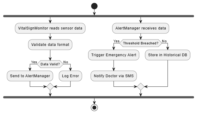
PlantUML Process View:
@startuml
start
fork
  :VitalSignMonitor reads sensor data;
  :Validate data format;
  if (Data Valid?) then (Yes)
    :Send to AlertManager;
  else (No)
    :Log Error;
  endif
fork again
  :AlertManager receives data;
  if (Threshold Breached?) then (Yes)
    :Trigger Emergency Alert;
    :Notify Doctor via SMS;
  else (No)
    :Store in Historical DB;
  endif
end fork
stop
@enduml
Tip: Use the Process View to identify bottlenecks. In MediTrack, ensuring that the AlertManager does not block during database writes is crucial for patient safety.
The Implementation View encompasses the components and files used to assemble and release the physical system. It addresses configuration management and the organization of reusable parts.
MediTrack.API.dll: Exposes RESTful endpoints for mobile apps.DataAccessLayer.jar: Handles database interactions and ORM mapping.SecurityModule.so: Provides encryption and authentication services.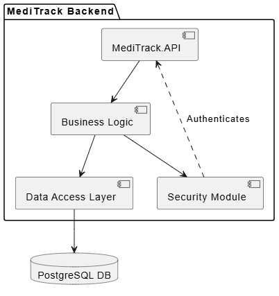
PlantUML Implementation View:
@startuml
package "MediTrack Backend" {
  component [MediTrack.API] as API
  component [Business Logic] as BL
  component [Data Access Layer] as DAL
  component [Security Module] as Sec
}

database "PostgreSQL DB" as DB

API --> BL
BL --> DAL
DAL --> DB
BL --> Sec
Sec ..> API : Authenticates
@enduml
Tip: Modularize components to enable independent deployment. In MediTrack, the Security Module can be updated without redeploying the entire API layer.
The Deployment View focuses on system engineering issues, describing the hardware nodes on which the system executes and the distribution of physical parts.
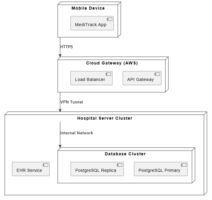
PlantUML Deployment View:
@startuml
node "Mobile Device" as Mobile {
  component [MediTrack App]
}

node "Cloud Gateway (AWS)" as Cloud {
  component [API Gateway]
  component [Load Balancer]
}

node "Hospital Server Cluster" as Hospital {
  component [EHR Service]
  node "Database Cluster" as DB {
    component [PostgreSQL Primary]
    component [PostgreSQL Replica]
  }
}

Mobile --> Cloud : HTTPS
Cloud --> Hospital : VPN Tunnel
Hospital --> DB : Internal Network
@enduml
Tip: Consider failover and redundancy in the Deployment View. For MediTrack, the Database Cluster uses replication to ensure data availability during server failures.
Architecting a software-intensive system like MediTrack is not about creating a single, monolithic blueprint. It is about constructing a multi-dimensional model that captures the system’s essence from various perspectives. The five interlocking views of UML—Use Case, Design, Process, Implementation, and Deployment—provide a structured framework to manage complexity, ensure alignment with stakeholder needs, and address technical risks.
By adopting this 360-degree approach, architects can bridge the gap between abstract requirements and concrete implementation. Each view acts as a lens, focusing on specific concerns while remaining interconnected with the others. In doing so, we transform complexity from a barrier into a manageable, structured challenge, ultimately delivering robust, scalable, and maintainable systems.
As software systems continue to evolve in complexity, the discipline of multi-view architectural modeling remains an indispensable tool for any serious software engineer or architect.