In the fast-paced world of software development, documentation often becomes a casualty of speed. Teams prioritize shipping features over maintaining visual representations of how systems work. Over time, this leads to architecture drift, where the codebase diverges significantly from the original design. Developers spend excessive time reverse-engineering legacy systems, and new joiners struggle to grasp the high-level flow of data.
The solution lies in finding the right balance between comprehensive documentation and practical maintainability. This is where the C4 Model enters the conversation. It offers a structured approach to documenting software architecture that scales with the complexity of the system, bridging the gap between abstract theory and concrete implementation.
For years, Unified Modeling Language (UML) dominated the landscape of system design. While powerful, standard UML diagrams often proved too verbose or too abstract for modern agile teams. The C4 Model provides a pragmatic middle ground. It focuses on four levels of abstraction, allowing architects to communicate effectively with stakeholders, developers, and operators without drowning them in irrelevant detail.
This comprehensive guide explores the C4 Model through both theoretical foundations and a complete, real-world case study of an E-Commerce Order Processing System. By examining each level with practical PlantUML examples, we'll demonstrate how to create living documentation that evolves with your codebase and serves as an invaluable resource for your entire team.
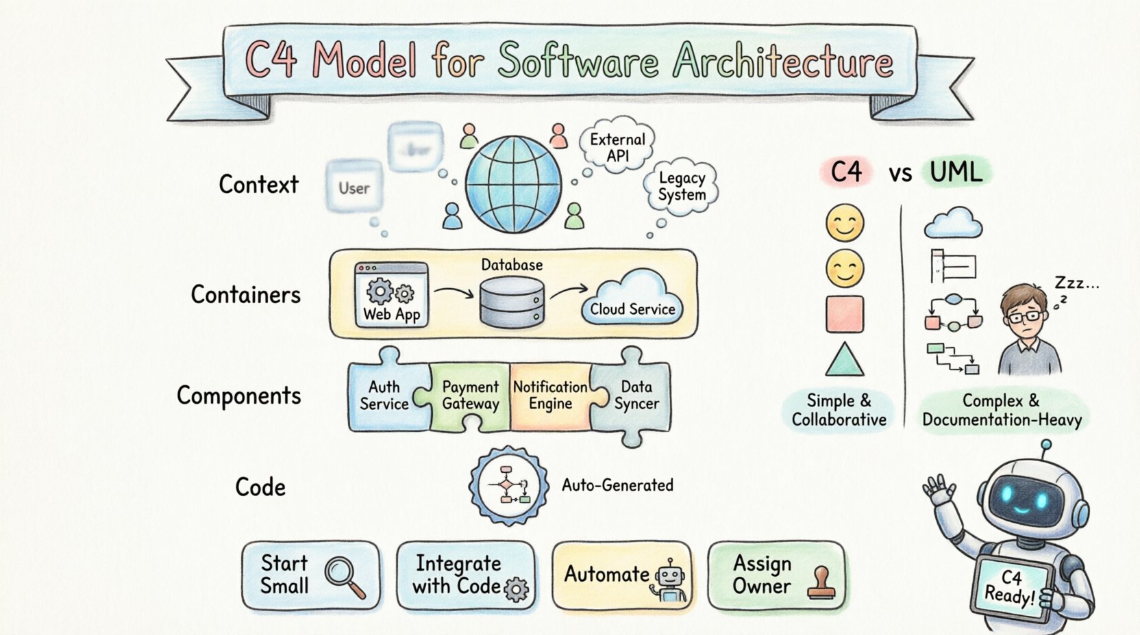
The C4 Model is not a tool, but a conceptual framework. It stands for Context, Containers, Components, and Code. Each level represents a different scope and audience, ensuring that the right people see the right information. The core philosophy is to start high-level and drill down only when necessary. This prevents the common pitfall of creating massive diagrams that no one reads.
Simplicity: It uses standard shapes to represent boxes and lines, avoiding complex notation.
Scalability: You can start with a single box and expand as the system grows.
Human-Centric: It prioritizes understanding over strict mathematical formalism.
Unlike traditional methods that might require a complete redesign every time a minor change occurs, C4 encourages documentation that evolves alongside the code. It acknowledges that perfect documentation is impossible, but useful documentation is achievable.
The strength of this model lies in its hierarchy. Each level serves a specific purpose and targets a specific group of readers. Understanding these distinctions is crucial for effective implementation.
| Level | Name | Primary Audience | Focus |
|---|---|---|---|
| 1 | System Context | Stakeholders, Managers | High-level boundaries and external systems |
| 2 | Container | Developers, Architects | Deployable units like apps or databases |
| 3 | Component | Developers | Internal structure within a container |
| 4 | Code | Developers | Class-level implementation details |
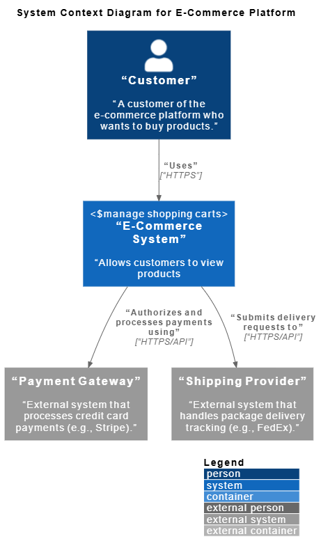
The first level is the System Context Diagram. This is the most critical diagram for establishing shared understanding. It answers the question: What is this system, and how does it fit into the wider world?
The System: Represented as a single box in the center.
People: External actors interacting with the system.
Systems: Other software that the system integrates with.
This diagram does not show internal workings. It focuses on data flow and boundaries. For example, a payment service might show connections to a banking API, a user database, and a notification service. This clarity helps stakeholders visualize dependencies without getting bogged down in microservices details.
Let's examine a complete E-Commerce Order Processing System. At the system context level, we identify the key actors and external dependencies:
Scenario Overview:
Customers browse products and place orders via a SPA Web App
Main System handles orders, inventory, and payments
External Systems include a Payment Gateway (Stripe) and a Shipping Provider (FedEx)
@startuml
!include https://raw.githubusercontent.com/plantuml-stdlib/C4-PlantUML/master/C4_Container.puml

LAYOUT_WITH_LEGEND()

title System Context Diagram for E-Commerce Platform

Person(customer, "Customer", "A customer of the e-commerce platform who wants to buy products.")
System(ecommerce_system, "E-Commerce System", "Allows customers to view products, manage shopping carts, and place orders.")
System_Ext(payment_gateway, "Payment Gateway", "External system that processes credit card payments (e.g., Stripe).")
System_Ext(shipping_provider, "Shipping Provider", "External system that handles package delivery tracking (e.g., FedEx).")

Rel(customer, ecommerce_system, "Uses", "HTTPS")
Rel(ecommerce_system, payment_gateway, "Authorizes and processes payments using", "HTTPS/API")
Rel(ecommerce_system, shipping_provider, "Submits delivery requests to", "HTTPS/API")
@endumlKey Insights from Level 1:
Single Point of Interaction: The customer interacts with one system boundary
Clear External Dependencies: Payment and shipping are handled by specialized third-party services
Technology Agnostic: No implementation details are exposed at this level
Stakeholder Friendly: Business stakeholders can understand system scope without technical knowledge
This diagram establishes the foundation for all subsequent levels. It defines what's inside our responsibility (the E-Commerce System) versus what's outside (external providers).
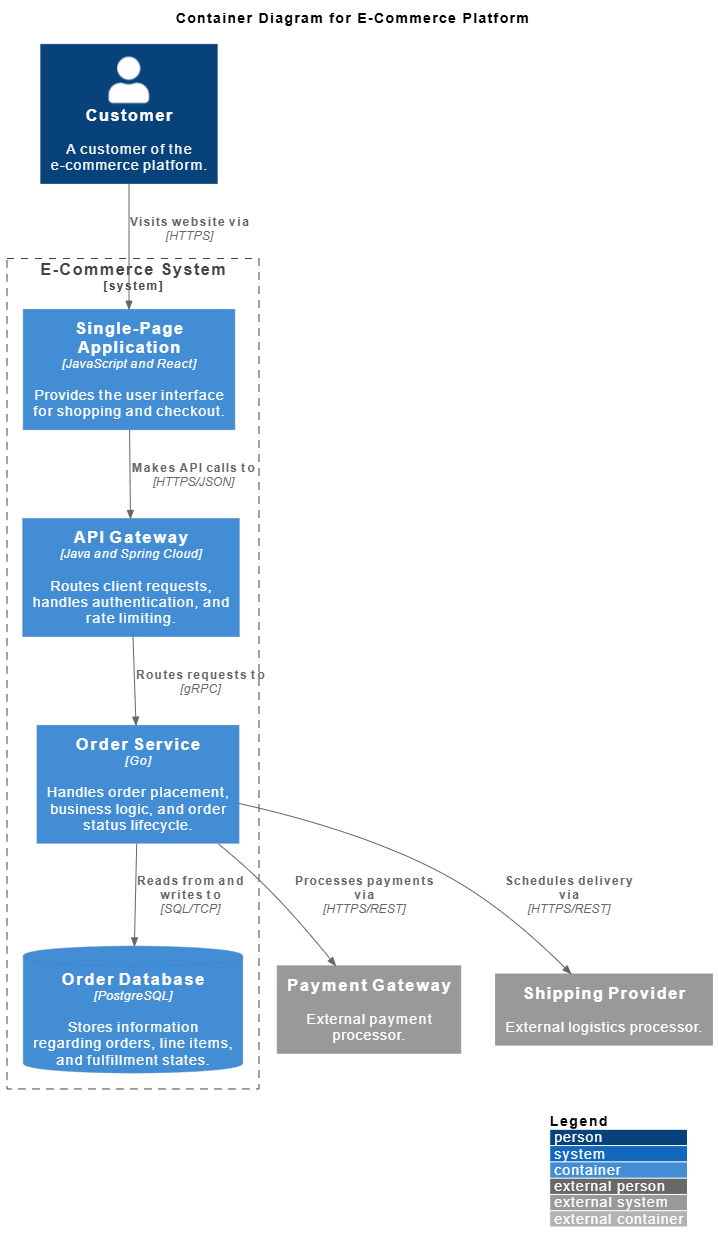
Once the context is clear, the second level breaks the central system into Containers. A container is a high-level deployable unit. This could be a web application, a mobile app, a database, or a serverless function.
Technology Agnostic: It describes the purpose, not the specific technology stack.
Communication: Lines between containers show how they talk (HTTP, gRPC, etc.).
Boundaries: It defines where the system ends and the infrastructure begins.
For a team building a microservices architecture, this level is vital. It maps out the network topology at an application level. It helps developers understand which parts of the system they need to interact with and which are owned by other teams.
Zooming into our E-Commerce System, we reveal the high-level technical building blocks:
@startuml
!include https://raw.githubusercontent.com/plantuml-stdlib/C4-PlantUML/master/C4_Container.puml

LAYOUT_WITH_LEGEND()

title Component Diagram for Order Service (Drill-Down)

' External Containers & Systems relative to Order Service
Container(api_gateway, "API Gateway", "Java and Spring Cloud", "Routes client requests, handles authentication, and rate limiting.")
ContainerDb(database, "Order Database", "PostgreSQL", "Stores information regarding orders, line items, and fulfillment states.")
System_Ext(payment_gateway, "Payment Gateway", "External payment processor.")
System_Ext(shipping_provider, "Shipping Provider", "External logistics processor.")

System_Boundary(order_service_boundary, "Order Service") {
Container(grpc_server, "gRPC Server / Controller", "Go / gRPC", "Exposes endpoints for order placement and status updates; handles incoming gRPC requests.")
Container(order_manager, "Order Manager", "Go", "Core domain component managing order validation, placement, and lifecycle states.")
Container(payment_client, "Payment Client", "Go / HTTP", "Integrates with the external Payment Gateway to process order payments.")
Container(shipping_client, "Shipping Client", "Go / HTTP", "Integrates with the external Shipping Provider to schedule deliveries.")
Container(repository, "Order Repository", "Go / Database Driver", "Handles data persistence abstraction; manages SQL transactions.")
}

' Incoming relations from API Gateway
Rel(api_gateway, grpc_server, "Sends order requests to", "gRPC")

' Internal Order Service relations
Rel(grpc_server, order_manager, "Invokes business logic via", "Go Functions")
Rel(order_manager, payment_client, "Triggers payment processing via", "Go Functions")
Rel(order_manager, shipping_client, "Triggers shipping scheduling via", "Go Functions")
Rel(order_manager, repository, "Persists order states via", "Go Functions")

' Outgoing relations to Database and External Systems
Rel(repository, database, "Reads from and writes to", "SQL/TCP")
Rel(payment_client, payment_gateway, "Processes payments via", "HTTPS/REST")
Rel(shipping_client, shipping_provider, "Schedules delivery via", "HTTPS/REST")

@endumlArchitectural Decisions Revealed:
Frontend-Backend Separation: React SPA communicates with backend through API Gateway
API Gateway Pattern: Centralized entry point handles cross-cutting concerns (auth, rate limiting)
Microservices Approach: Order Service is isolated as a dedicated Go service
Database Per Service: PostgreSQL dedicated to order data
Communication Protocols: gRPC for internal services, HTTPS/REST for external integrations
Team Ownership Implications:
Frontend team owns the Single-Page Application
Platform team manages the API Gateway
Backend team develops the Order Service
DevOps team maintains the PostgreSQL database
This level provides the blueprint for development teams to understand system topology and integration points.
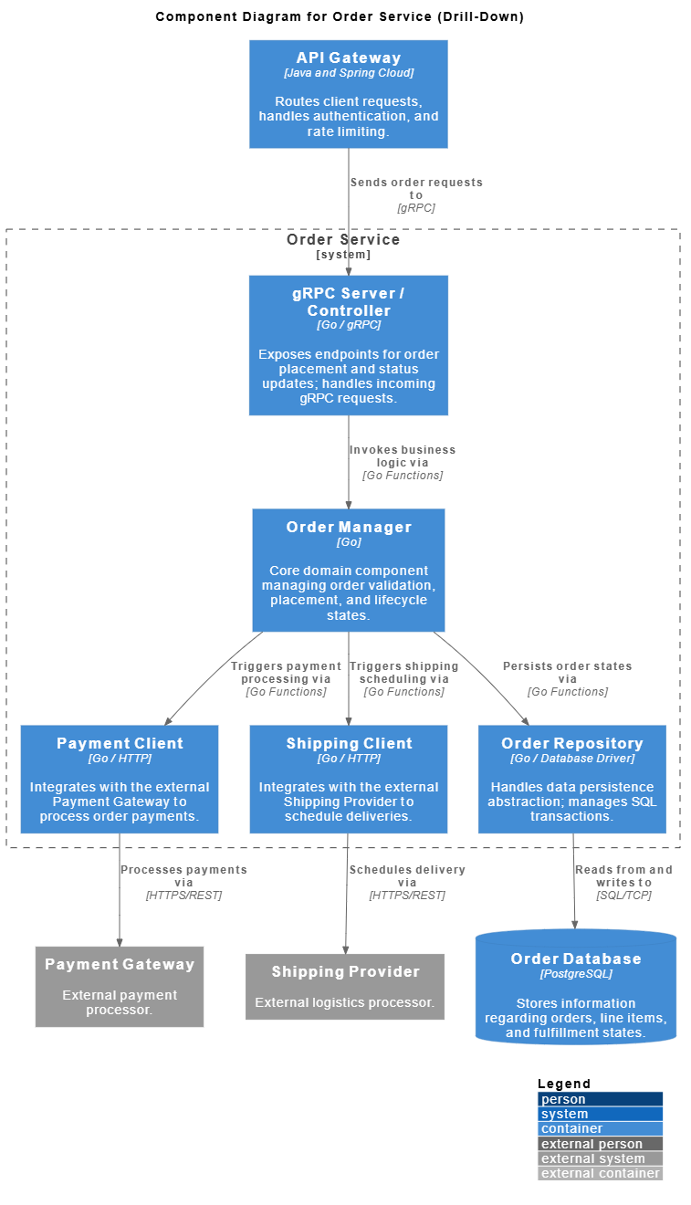
Inside a container, the system is often too complex to manage. The third level, Components, decomposes a container into smaller, cohesive parts. A component is a logical grouping of functionality.
Responsibility: Each component has a clear job, like handling authentication or processing orders.
Interfaces: It defines how other components interact with it.
Decoupling: It highlights dependencies and separation of concerns.
This level is where most day-to-day development decisions happen. It helps teams identify high coupling or circular dependencies before they become technical debt. It bridges the gap between high-level architecture and actual code structure.
Drilling into the Order Service container, we expose its internal structural components:
@startuml

!include  https://raw.githubusercontent.com/plantuml-stdlib/C4-PlantUML/master/C4_Container.puml
LAYOUT_WITH_LEGEND()

title Component Diagram for Order Service (Drill-Down)

' External Containers & Systems relative to Order Service

Container(api_gateway, "API Gateway", "Java and Spring Cloud", "Routes client requests, handles authentication, and rate limiting.")
ContainerDb(database, "Order Database", "PostgreSQL", "Stores information regarding orders, line items, and fulfillment states.")
System_Ext(payment_gateway, "Payment Gateway", "External payment processor.")
System_Ext(shipping_provider, "Shipping Provider", "External logistics processor.")
System_Boundary(order_service_boundary, "Order Service") {
    Container(grpc_server, "gRPC Server / Controller", "Go / gRPC", "Exposes endpoints for order placement and status updates; handles incoming gRPC requests.")
    Container(order_manager, "Order Manager", "Go", "Core domain component managing order validation, placement, and lifecycle states.")
    Container(payment_client, "Payment Client", "Go / HTTP", "Integrates with the external Payment Gateway to process order payments.")
    Container(shipping_client, "Shipping Client", "Go / HTTP", "Integrates with the external Shipping Provider to schedule deliveries.")
    Container(repository, "Order Repository", "Go / Database Driver", "Handles data persistence abstraction; manages SQL transactions.")
}

' Incoming relations from API Gateway
Rel(api_gateway, grpc_server, "Sends order requests to", "gRPC")

' Internal Order Service relations
Rel(grpc_server, order_manager, "Invokes business logic via", "Go Functions")
Rel(order_manager, payment_client, "Triggers payment processing via", "Go Functions")
Rel(order_manager, shipping_client, "Triggers shipping scheduling via", "Go Functions")
Rel(order_manager, repository, "Persists order states via", "Go Functions")

' Outgoing relations to Database and External Systems
Rel(repository, database, "Reads from and writes to", "SQL/TCP")
Rel(payment_client, payment_gateway, "Processes payments via", "HTTPS/REST")
Rel(shipping_client, shipping_provider, "Schedules delivery via", "HTTPS/REST")

@endumlComponent Responsibilities:
Order Controller: REST API layer, request/response handling, input validation
Order Manager: Core business logic, state machine orchestration, rule validation
Payment Client: External service abstraction, retry logic, error handling
Order Repository: Data persistence, query optimization, transaction management
Design Patterns in Action:
Layered Architecture: Clear separation between API, business logic, and data access
Dependency Injection: Order Manager depends on interfaces (Repository, Client) not implementations
Single Responsibility: Each component has one well-defined purpose
Hexagonal Architecture: Business logic isolated from external concerns
Development Workflow Benefits:
Frontend developers can work with Order Controller endpoints
Business analysts can review Order Manager logic
Database engineers can optimize Order Repository queries
Integration specialists can enhance Payment Client
This level serves as the blueprint for sprint planning and task allocation.
The fourth level is rarely needed for most teams, but it exists for completeness. Code Diagrams show class structures and relationships. In modern object-oriented or functional programming, these diagrams are often generated automatically from the source code.
Implementation Detail: Shows classes, methods, and attributes.
Maintenance: Best kept as part of automated documentation tools.
Usage: Useful for onboarding new developers to a specific codebase.
Most teams skip this level in manual documentation because it changes too frequently. If the code changes, the diagram changes. Relying on code analysis tools for this level is generally more effective than manual drawing.
Zooming into the Order Manager component, we reveal the actual code-level structure:
@startuml
!include  https://raw.githubusercontent.com/plantuml-stdlib/C4-PlantUML/master/C4_Container.puml

title Code Diagram for Order Manager Internal Logic

interface OrderProcessor {
    +CreateOrder(cart Cart) Order
    +CancelOrder(orderID string) error
}

class OrderManager {
    -repo OrderRepository
    -paymentClient PaymentClient
    +CreateOrder(cart Cart) Order
    +CancelOrder(orderID string) error
    -validateStock(cart Cart) bool
}

interface OrderRepository {
    +Save(order Order) error
    +FindByID(id string) (Order, error)
}

interface PaymentClient {
    +Charge(amount float64) bool
}

OrderProcessor <|.. OrderManager : Implements
OrderManager --> OrderRepository : Uses dependency injection
OrderManager --> PaymentClient : Uses dependency injection
@endumlImplementation Patterns:
Interface Segregation: OrderProcessor defines the public contract
Dependency Injection: OrderManager receives dependencies through constructor
Encapsulation: Private methods (validateStock) hidden from external consumers
SOLID Principles: Open/Closed principle allows extending without modifying
When to Use Level 4:
Onboarding new team members to complex business logic
Documenting design decisions for critical components
Code review discussions about architecture
Refactoring planning sessions
Automation Recommendation:
Generate these diagrams automatically using tools like:
Go: godoc with visualization plugins
Java: Javadoc with UML generators
TypeScript: TypeDoc with diagram extensions
Manual maintenance of Level 4 diagrams is rarely sustainable. Focus manual effort on Levels 1-3.
Why choose C4 over the industry-standard UML? The answer lies in maintenance and cognitive load. UML diagrams are often overly complex, requiring a certification to read and draw correctly. C4 uses standard shapes that anyone can understand.
| Feature | C4 Model | Traditional UML |
|---|---|---|
| Complexity | Low. Standard shapes. | High. Many specific symbols. |
| Maintainability | High. Easy to update. | Low. Hard to keep in sync. |
| Readability | High for non-technical staff. | Low. Technical jargon heavy. |
| Flexibility | Focuses on structure. | Focuses on behavior/state. |
UML excels in describing complex state transitions or behavioral sequences. However, for high-level system architecture, C4 is often more practical. It removes the barrier to entry, allowing architects to focus on design rather than notation rules.
Adopting this model requires a shift in mindset. It is not about creating a massive repository of images. It is about creating living documentation that supports the team.
Start Small: Begin with the System Context diagram. If that is too much, just document the system name and purpose.
Integrate with Code: Store diagrams in the same repository as the code. This ensures version control and review processes apply to documentation.
Automate Where Possible: Use tools that generate diagrams from code or configuration files to reduce manual overhead.
Define Ownership: Assign a specific person or team to maintain the diagrams. Documentation without ownership becomes stale quickly.
The goal is to make documentation a byproduct of development, not a separate task. If a feature changes, the diagram should change as part of the same pull request.
Week 1-2: Foundation
Create System Context diagram (Level 1)
Review with stakeholders and product owners
Store in /docs/architecture/context.puml
Week 3-4: Technical Blueprint
Develop Container diagram (Level 2)
Align with development teams on service boundaries
Store in /docs/architecture/containers.puml
Week 5-8: Detailed Design
Build Component diagrams (Level 3) for critical services
Use during sprint planning and technical discussions
Store in /docs/architecture/components/order-service.puml
Ongoing: Maintenance
Update diagrams as part of feature development
Automate Level 4 generation from code
Review quarterly during architecture retrospectives
Transitioning to this model comes with challenges. Teams often struggle with the initial investment of time and the fear of creating more work.
Perfectionism: Trying to document every single component leads to burnout. Accept that diagrams will be incomplete.
Tooling Friction: Manual drawing tools can be slow. Look for solutions that integrate with your existing workflow.
Resistance to Change: Senior developers may prefer their own mental models. Explain the benefits of shared understanding to overcome this.
Version Control: Binary diagram files are hard to compare. Use text-based formats for diagrams whenever possible.
It is important to recognize that documentation is a communication tool, not a legal contract. Its value is in the shared mental model it creates between team members. If the diagram helps a developer understand a system faster, it has succeeded.
Challenge 1: Multiple Teams, Multiple Perspectives
Solution: Create separate views for frontend, backend, and DevOps teams
Implementation: Use PlantUML's !include to share common elements
Challenge 2: Rapidly Changing External Integrations
Solution: Abstract external systems at Level 1, detail at Level 3
Implementation: Payment Client component can evolve without changing system context
Challenge 3: Scaling to Multiple Services
Solution: Create one Component diagram per service
Implementation: Order Service, Inventory Service, Notification Service each get their own Level 3 diagram
Artificial intelligence is beginning to reshape how we create architecture documentation. AI tools can analyze codebases and suggest component structures. This reduces the manual effort required to keep diagrams up to date.
Automated Extraction: AI can parse code repositories to identify boundaries and dependencies.
Suggestion Engines: Tools can recommend where a container fits in the system context.
Change Detection: AI can flag when the code deviates from the documented architecture.
While AI is powerful, it cannot replace human judgment. An architect must still decide what is important to show and what to hide. AI handles the mechanics; humans handle the strategy.
Automated Tasks:
Scan Go code to detect new components in Order Service
Analyze database schemas to update Container diagrams
Monitor API gateway logs to identify new external dependencies
Human Oversight:
Decide which components warrant documentation
Validate AI-suggested relationships make business sense
Ensure diagrams remain readable and not overly detailed
Tools to Consider:
Structurizr: Automated C4 diagram generation from code
Code2Flow: Convert source code to flowcharts
PlantUML AI plugins: Natural language to diagram conversion
The biggest enemy of architecture documentation is time. Systems evolve, and old diagrams become misleading. To combat this, teams must adopt a culture of documentation hygiene.
Review Cycles: Schedule regular reviews of diagrams during sprint planning or retrospectives.
Onboarding: Use the diagrams as part of the onboarding process for new hires. If they are useful for learning, they are useful for the team.
Minimal Viable Documentation: Focus on the 20% of diagrams that provide 80% of the value. Ignore the rest.
By treating diagrams as code, teams can apply the same rigor to their documentation. This includes code reviews, automated testing of diagram consistency, and continuous integration pipelines that verify the diagrams match the code.
Every Sprint:
Update Component diagrams when new features are added
Review Level 3 diagrams during code review
Every Release:
Validate Container diagrams reflect deployed architecture
Update external system integrations at Level 1
Every Quarter:
Full architecture review with all stakeholders
Retire outdated diagrams, consolidate overlapping views
Onboarding New Developers:
Use Level 2 diagrams for system overview (Day 1)
Dive into Level 3 diagrams for service-specific training (Week 1)
Reference Level 4 diagrams for deep-dive sessions (Month 1)
Investing in clear architecture documentation pays dividends over the lifecycle of a project. It reduces the cost of change. When you know how the pieces fit together, you can modify them with less fear of breaking dependencies.
Reduced Cognitive Load: New developers spend less time asking questions.
Faster Onboarding: Visual aids accelerate the learning curve.
Better Communication: Stakeholders get a clear picture without technical jargon.
Improved Decision Making: Architecture decisions are recorded and explained.
The choice to adopt this model is not about following a trend. It is about recognizing that software is a communication medium. The code communicates with the machine, but the diagrams communicate with the people building and maintaining the code. As systems grow in complexity, the need for clear, structured communication becomes critical.
Before C4 Implementation:
New developer onboarding: 6-8 weeks to productivity
Architecture questions per week: 15-20
Undocumented system behavior incidents: 5-7 per quarter
Time to understand impact of changes: 2-3 days
After C4 Implementation (6 months):
New developer onboarding: 3-4 weeks to productivity
Architecture questions per week: 5-7
Undocumented system behavior incidents: 1-2 per quarter
Time to understand impact of changes: 2-4 hours
ROI Calculation:
Time saved per developer per month: ~20 hours
Team of 10 developers: 200 hours/month
Annual savings: 2,400 hours or ~$120,000 (at $50/hour)
Investment in documentation: ~200 hours initial + 40 hours/month maintenance
Net benefit: Positive within 3 months
The journey from chaotic, outdated documentation to a structured, living architecture practice is not trivial, but it is achievable. The C4 Model provides the framework, but success depends on consistent execution and cultural adoption.
Through our E-Commerce Order Processing System case study, we've demonstrated how each level of the C4 Model serves a distinct purpose:
Level 1 (Context) establishes shared understanding with stakeholders
Level 2 (Containers) provides the technical blueprint for development teams
Level 3 (Components) enables detailed design and sprint planning
Level 4 (Code) supports onboarding and deep technical discussions
The key insight is that documentation should be just enough, just in time, and just for the audience. You don't need to document everything at once. Start with the System Context diagram. Get stakeholder buy-in. Then progressively elaborate as the system grows and team needs evolve.
This Week:
Identify your most critical system
Draft a Level 1 Context diagram using PlantUML
Share it with one stakeholder for feedback
This Month:
Create Level 2 Container diagrams for your core services
Store diagrams in version control alongside code
Use diagrams in one architecture discussion or onboarding session
This Quarter:
Develop Level 3 Component diagrams for high-complexity services
Establish documentation review cadence
Measure time saved in onboarding or decision-making
This Year:
Automate Level 4 diagram generation
Integrate diagram validation into CI/CD pipelines
Share your C4 practice with other teams in your organization
Whether C4 becomes the universal standard is less important than whether it solves the specific problems your team faces. If it helps you build better systems and understand them better, it has done its job. The future of architecture documentation lies in tools and practices that reduce the friction of keeping information current. Models that prioritize clarity over complexity will naturally rise to the top.
The E-Commerce platform we've explored demonstrates that C4 is not just theoretical—it's practical, scalable, and immediately applicable. Your system may differ in domain, technology stack, or scale, but the principles remain the same: start high-level, drill down when necessary, and always keep your audience in mind.
Begin your C4 journey today. Your future self—and your future teammates—will thank you.
Ready to implement C4 in your organization? Start with the System Context diagram for your most critical system. Use PlantUML for version-controlled, text-based diagrams. Share it with your team this week. Small steps lead to lasting change.