
In today's rapidly evolving technological landscape, systems development faces an ever-present challenge: complexity. As systems grow in size and sophistication, they become increasingly difficult to understand, build, and maintain. This complexity stems from what experts call the "vicious circle" of constant change combined with the use of intricate technologies. Without proper management, this complexity can quickly spiral into chaos, leading to project failures, budget overruns, and frustrated teams.
The solution lies in modeling. Models serve as the primary tool for organization and communication in systems development, acting as a bridge between abstract ideas and concrete implementations. Just as architects use blueprints to design buildings before construction begins, systems developers use models to visualize, specify, and guide the creation of complex systems.
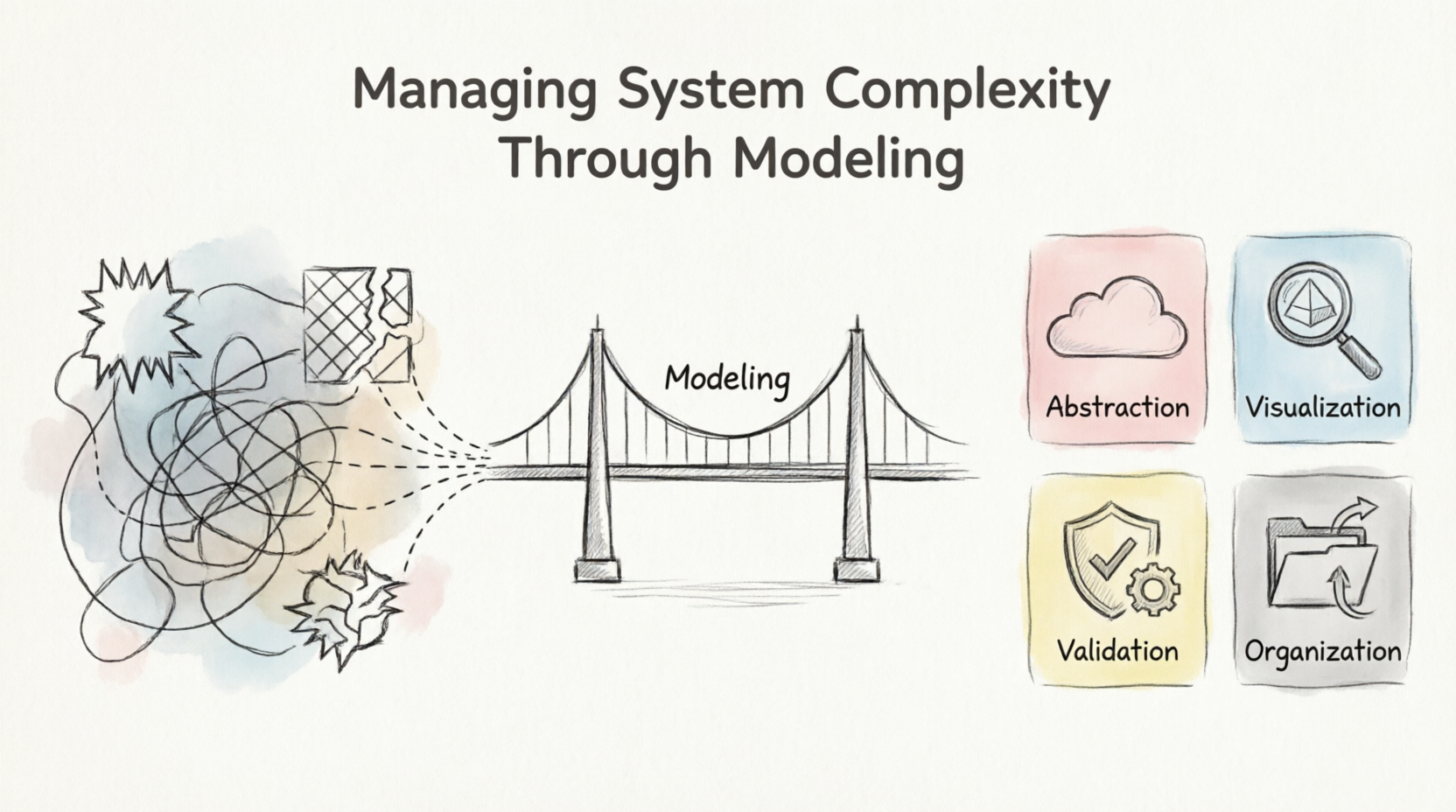
This comprehensive guide explores how models help manage system complexity, providing beginners with the foundational knowledge and practical examples needed to leverage modeling effectively in their development projects. Through abstraction, visualization, validation, communication, and organization, models transform overwhelming complexity into manageable, understandable components.
What is Abstraction?
Abstraction is the cornerstone technique that enables models to manage complexity effectively. It involves focusing on essential information required to understand a subject while deliberately excluding irrelevant or incidental details that might cause confusion or cognitive overload.
Think of abstraction as a filtering mechanism that allows you to see the forest without getting lost among the trees. By choosing the appropriate level of detail, you can understand systems at different scales without being overwhelmed.
How Abstraction Works:
High-level abstraction: Shows the big picture, omitting fine details
Low-level abstraction: Reveals intricate details necessary for specific tasks
Context-dependent: The "right" level depends on what you're trying to accomplish
Examples:
Example 1: Automotive Systems
Level 1 (Vehicle): A car has an engine, wheels, steering, and brakes
Level 2 (Engine System): The engine contains cylinders, pistons, fuel injection, and ignition systems
Level 3 (Piston Assembly): A piston includes rings, connecting rods, pins, and lubrication channels
Level 4 (Material Science): The piston ring composition, metallurgy, and manufacturing tolerances
Example 2: E-Commerce Platform
Level 1 (Business View): Customers browse products, add to cart, and checkout
Level 2 (System Architecture): Web server, database, payment gateway, inventory system
Level 3 (Component Level): Authentication module, shopping cart service, order processing engine
Level 4 (Code Level): Functions, classes, algorithms, and data structures
Example 3: University Management System
Level 1 (Stakeholder View): Students enroll in courses, professors teach, administrators manage records
Level 2 (Functional View): Registration system, grading system, scheduling system, billing system
Level 3 (Technical View): APIs, databases, user interfaces, integration points
PlantUML Diagram: Levels of Abstraction
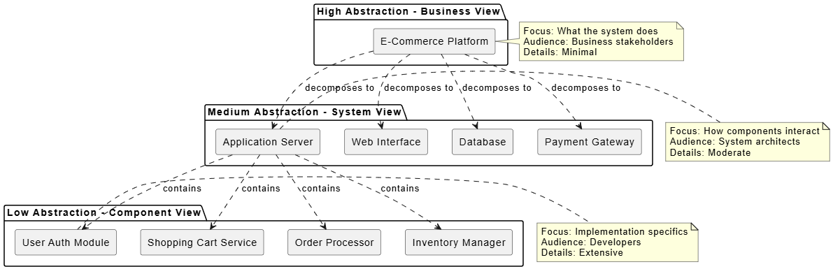
@startuml
skinparam backgroundColor #FFFFFF
skinparam componentStyle rectangle

package "High Abstraction - Business View" {
  component [E-Commerce Platform] as platform
}

package "Medium Abstraction - System View" {
  component [Web Interface] as web
  component [Application Server] as app
  component [Database] as db
  component [Payment Gateway] as payment
}

package "Low Abstraction - Component View" {
  component [User Auth Module] as auth
  component [Shopping Cart Service] as cart
  component [Order Processor] as order
  component [Inventory Manager] as inventory
}

platform ..> web : decomposes to
platform ..> app : decomposes to
platform ..> db : decomposes to
platform ..> payment : decomposes to

app ..> auth : contains
app ..> cart : contains
app ..> order : contains
app ..> inventory : contains

note right of platform
  Focus: What the system does
  Audience: Business stakeholders
  Details: Minimal
end note

note right of app
  Focus: How components interact
  Audience: System architects
  Details: Moderate
end note

note right of auth
  Focus: Implementation specifics
  Audience: Developers
  Details: Extensive
end note

@enduml
Example: Healthcare Management System
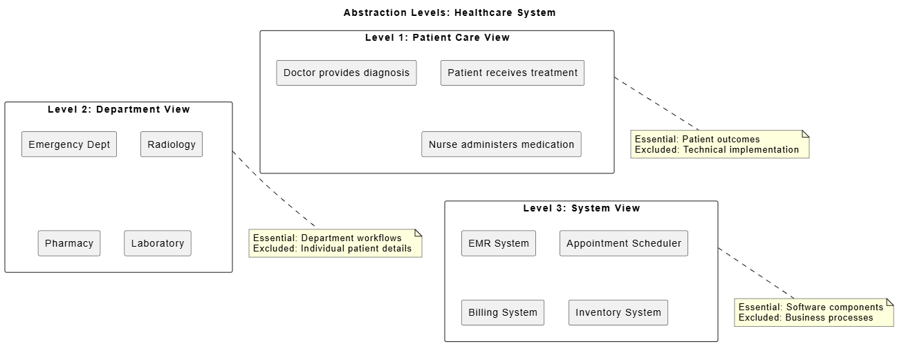
@startuml
skinparam backgroundColor #FFFFFF

title "Abstraction Levels: Healthcare System"

rectangle "Level 1: Patient Care View" as L1 {
  rectangle "Patient receives treatment" as p1
  rectangle "Doctor provides diagnosis" as p2
  rectangle "Nurse administers medication" as p3
}

rectangle "Level 2: Department View" as L2 {
  rectangle "Emergency Dept" as ed
  rectangle "Radiology" as rad
  rectangle "Pharmacy" as ph
  rectangle "Laboratory" as lab
}

rectangle "Level 3: System View" as L3 {
  rectangle "EMR System" as emr
  rectangle "Appointment Scheduler" as appt
  rectangle "Billing System" as bill
  rectangle "Inventory System" as inv
}

L1 -[hidden]-> L2
L2 -[hidden]-> L3

note bottom of L1
  Essential: Patient outcomes
  Excluded: Technical implementation
end note

note bottom of L2
  Essential: Department workflows
  Excluded: Individual patient details
end note

note bottom of L3
  Essential: Software components
  Excluded: Business processes
end note

@enduml
Key Takeaway: Abstraction allows you to manage complexity by revealing only what's necessary for a particular purpose, hiding the rest until needed.
What is a System Blueprint?
A model acts as a blueprint of a system, providing a simplified representation of reality that guides development. Just as architectural blueprints enable builders to construct complex buildings from two-dimensional drawings, system models enable developers to build sophisticated software and hardware systems from abstract representations.
Primary Functions of Blueprints:
Visualization: Using the "mind's eye" to detect patterns and relationships
Specification: Defining exactly what is required and how requirements will be met
Construction Guidance: Providing step-by-step direction for building the physical system
Examples:
Example 1: Mobile Banking Application Blueprint
Visualization Aspect:
User journey maps showing how customers navigate the app
Data flow diagrams illustrating how transactions are processed
Component diagrams revealing how different services interact
Specification Aspect:
Functional requirements: "Users must be able to transfer funds between accounts"
Non-functional requirements: "System must process transactions within 2 seconds"
Security requirements: "All data must be encrypted using AES-256"
Construction Guidance:
API specifications for backend services
Database schemas for storing user data
UI/UX wireframes for frontend development
Example: Smart Home System Blueprint
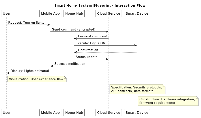
@startuml
skinparam backgroundColor #FFFFFF
skinparam sequence {
  LifeLineBackgroundColor #FFFFFF
  ParticipantBackgroundColor #FFFFFF
}

title "Smart Home System Blueprint - Interaction Flow"

participant "User" as User
participant "Mobile App" as App
participant "Home Hub" as Hub
participant "Cloud Service" as Cloud
participant "Smart Device" as Device

User -> App : Request: Turn on lights
App -> Cloud : Send command (encrypted)
Cloud -> Hub : Forward command
Hub -> Device : Execute: Lights ON
Device --> Hub : Confirmation
Hub --> Cloud : Status update
Cloud --> App : Success notification
App --> User : Display: Lights activated

note right of User
  Visualization: User experience flow
end note

note right of Cloud
  Specification: Security protocols,
  API contracts, data formats
end note

note right of Device
  Construction: Hardware integration,
  firmware requirements
end note

@enduml
Example: E-Learning Platform Blueprint
Visualization Diagram:
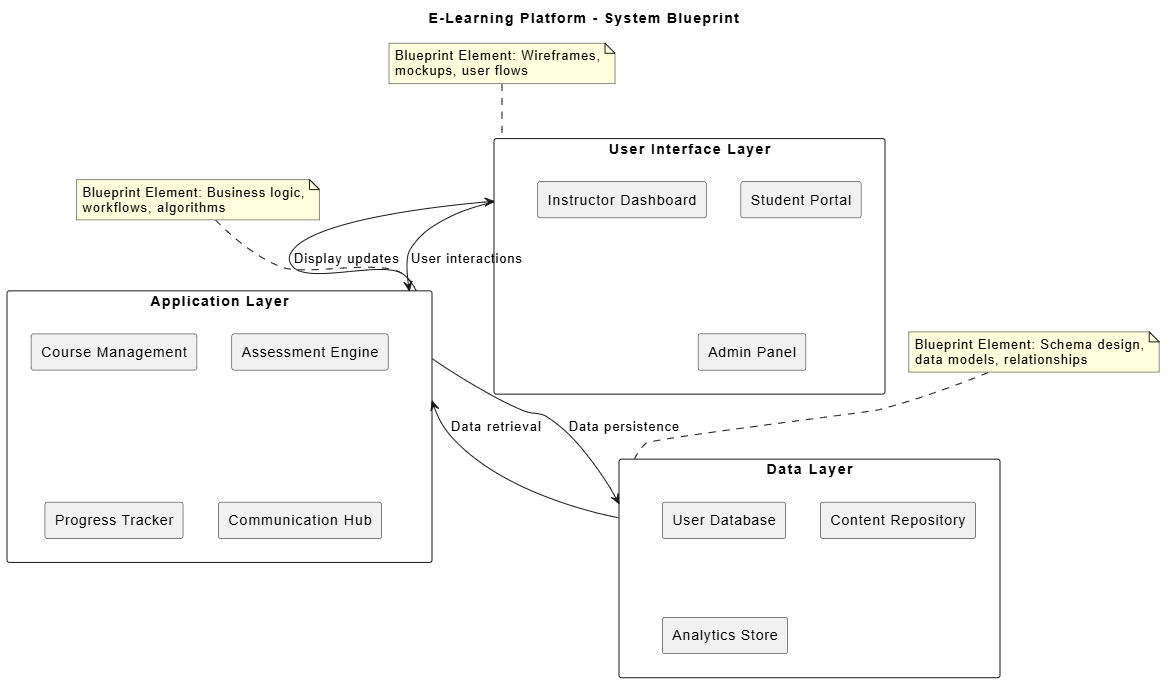
@startuml
skinparam backgroundColor #FFFFFF

title "E-Learning Platform - System Blueprint"

rectangle "User Interface Layer" as UI {
  rectangle "Student Portal" as student
  rectangle "Instructor Dashboard" as instructor
  rectangle "Admin Panel" as admin
}

rectangle "Application Layer" as APP {
  rectangle "Course Management" as course
  rectangle "Assessment Engine" as assess
  rectangle "Progress Tracker" as progress
  rectangle "Communication Hub" as comm
}

rectangle "Data Layer" as DATA {
  rectangle "User Database" as users
  rectangle "Content Repository" as content
  rectangle "Analytics Store" as analytics
}

UI --> APP : User interactions
APP --> DATA : Data persistence
DATA --> APP : Data retrieval
APP --> UI : Display updates

note top of UI
  Blueprint Element: Wireframes,
  mockups, user flows
end note

note top of APP
  Blueprint Element: Business logic,
  workflows, algorithms
end note

note top of DATA
  Blueprint Element: Schema design,
  data models, relationships
end note

@enduml
Example: Restaurant Management System
Blueprint Components:
Visual Model: Floor plan showing kitchen layout, dining area, POS terminal locations
Specification Document:
Table turnover time: 45 minutes average
Order accuracy: 99.5% target
Payment processing: Under 30 seconds
Construction Guide:
Network topology for POS systems
Kitchen display system integration
Inventory tracking automation
Key Takeaway: Blueprints transform abstract ideas into concrete plans, providing multiple views of the system that serve different purposes throughout the development lifecycle.
Why Validate Early?
Building complex systems is expensive and time-consuming. Models enable teams to verify their understanding and conduct experiments before committing significant resources to actual construction. This early validation is crucial for identifying problems when they're cheap to fix rather than discovering them after implementation when changes are costly.
Benefits of Model-Based Validation:
Feasibility Testing: Determine if a design can actually work
Constraint Verification: Ensure safety, usability, and performance requirements are met
Cost Savings: Changes to models are orders of magnitude cheaper than changes to physical systems
Risk Reduction: Identify potential failures before they occur
Examples:
Example 1: Autonomous Vehicle System
Validation Through Modeling:
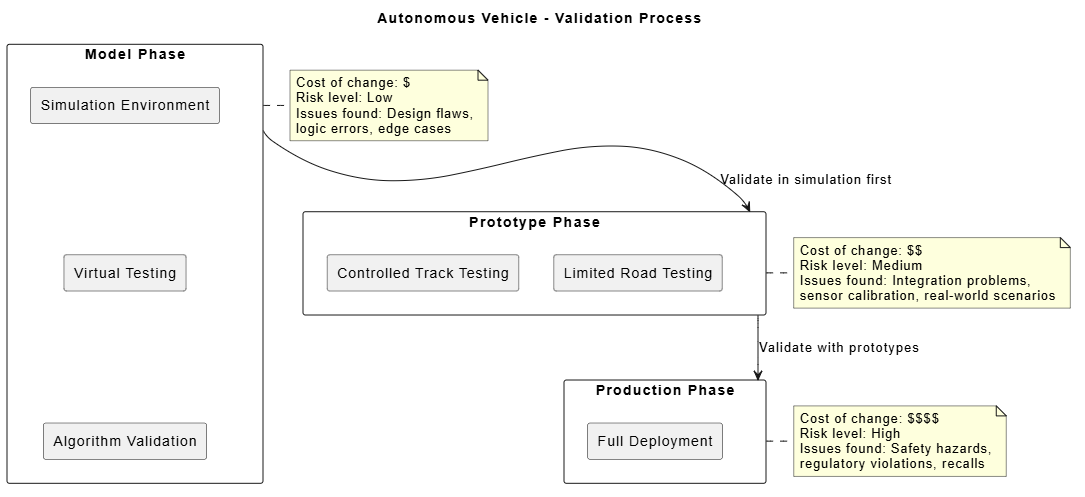
@startuml
skinparam backgroundColor #FFFFFF

title "Autonomous Vehicle - Validation Process"

rectangle "Model Phase" as MODEL {
  rectangle "Simulation Environment" as sim
  rectangle "Virtual Testing" as virtual
  rectangle "Algorithm Validation" as algo
}

rectangle "Prototype Phase" as PROTO {
  rectangle "Controlled Track Testing" as track
  rectangle "Limited Road Testing" as limited
}

rectangle "Production Phase" as PROD {
  rectangle "Full Deployment" as full
}

MODEL --> PROTO : Validate in simulation first
PROTO --> PROD : Validate with prototypes

note right of MODEL
  Cost of change: $
  Risk level: Low
  Issues found: Design flaws,
  logic errors, edge cases
end note

note right of PROTO
  Cost of change: $$
  Risk level: Medium
  Issues found: Integration problems,
  sensor calibration, real-world scenarios
end note

note right of PROD
  Cost of change: $$$$
  Risk level: High
  Issues found: Safety hazards,
  regulatory violations, recalls
end note

sim -[hidden]-> virtual
virtual -[hidden]-> algo

@enduml
Validation Activities:
Simulation Testing: Run millions of virtual miles to test edge cases
Scenario Modeling: Test rare but critical situations (pedestrian suddenly appears)
Performance Analysis: Verify response times meet safety requirements
Failure Mode Analysis: Identify what happens when sensors fail
Example 2: Financial Trading Platform
Early Validation Examples:
Model-Based Testing:
Create transaction flow models to verify no money can be lost in system failures
Simulate high-frequency trading scenarios to ensure system can handle peak loads
Model regulatory compliance requirements before writing code
Cost Comparison:
Model Change: $100-1,000 (update diagrams, rerun simulations)
Code Change: $1,000-10,000 (developer time, testing, deployment)
Production Fix: $100,000-10,000,000 (downtime, data recovery, legal liability)
Example 3: Hospital Patient Monitoring System
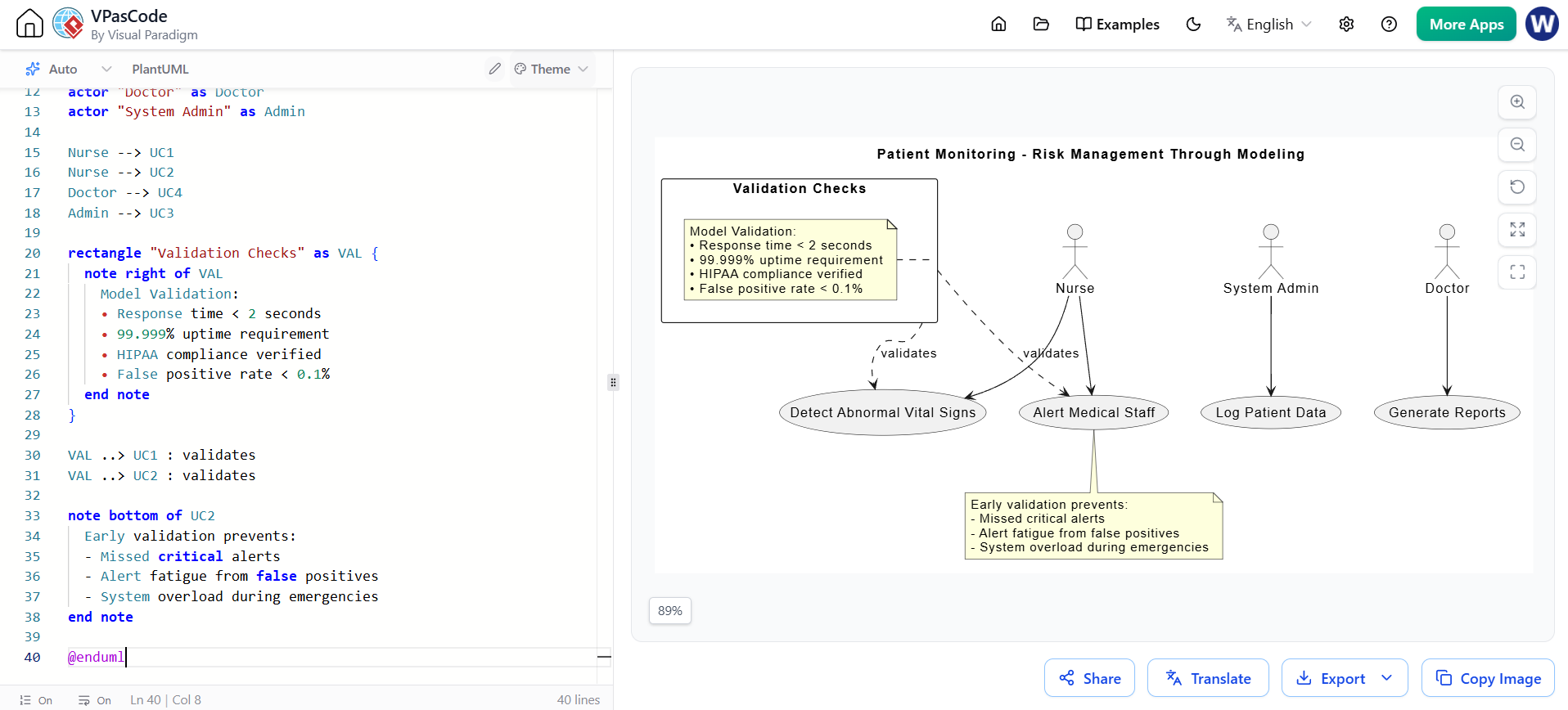
@startuml
skinparam backgroundColor #FFFFFF

title "Patient Monitoring - Risk Management Through Modeling"

usecase "Detect Abnormal Vital Signs" as UC1
usecase "Alert Medical Staff" as UC2
usecase "Log Patient Data" as UC3
usecase "Generate Reports" as UC4

actor "Nurse" as Nurse
actor "Doctor" as Doctor
actor "System Admin" as Admin

Nurse --> UC1
Nurse --> UC2
Doctor --> UC4
Admin --> UC3

rectangle "Validation Checks" as VAL {
  note right of VAL
    Model Validation:
    • Response time < 2 seconds
    • 99.999% uptime requirement
    • HIPAA compliance verified
    • False positive rate < 0.1%
    • Battery backup: 4 hours minimum
  end note
}

VAL ..> UC1 : validates
VAL ..> UC2 : validates

note bottom of UC2
  Early validation prevents:
  - Missed critical alerts
  - Alert fatigue from false positives
  - System overload during emergencies
end note

@enduml
Example 4: Cloud Migration Project
Validation Through Modeling:
Before Migration (Model Phase):
Create architecture diagrams showing new cloud infrastructure
Model data flow between on-premises and cloud systems
Simulate load patterns to size resources correctly
Calculate estimated costs using pricing models
Risks Identified Early:
Bandwidth limitations for data transfer
Compliance issues with data residency
Integration challenges with legacy systems
Skills gaps in team for cloud technologies
Key Takeaway: Models serve as safe, inexpensive sandboxes where you can test ideas, identify problems, and validate assumptions before committing to expensive implementation.
The Communication Challenge
Complexity is often compounded when different stakeholders have different understandings of a project. Developers, business analysts, managers, customers, and end-users all bring different perspectives, terminology, and priorities. Models provide a common language that bridges these gaps, enabling effective collaboration.
How Models Enhance Communication:
Create Shared Understanding: Visual representations are easier to understand than text alone
Establish Agreement: Help stakeholders agree on the level of detail and scope
Document Knowledge: Capture decisions and rationale throughout development
Reduce Ambiguity: Precise diagrams leave less room for misinterpretation
Examples:
Example 1: Cross-Functional Team Communication
Stakeholder Communication Matrix:
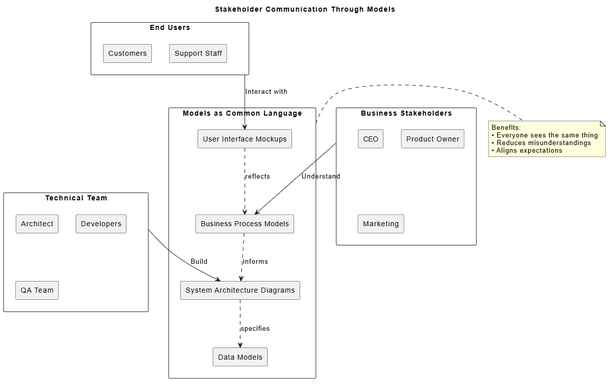
@startuml
skinparam backgroundColor #FFFFFF

title "Stakeholder Communication Through Models"

rectangle "Business Stakeholders" as BIZ {
  rectangle "CEO" as ceo
  rectangle "Product Owner" as po
  rectangle "Marketing" as mkt
}

rectangle "Technical Team" as TECH {
  rectangle "Architect" as arch
  rectangle "Developers" as dev
  rectangle "QA Team" as qa
}

rectangle "End Users" as USERS {
  rectangle "Customers" as cust
  rectangle "Support Staff" as support
}

rectangle "Models as Common Language" as MODELS {
  rectangle "Business Process Models" as bpm
  rectangle "System Architecture Diagrams" as arch_diag
  rectangle "User Interface Mockups" as ui
  rectangle "Data Models" as data
}

BIZ --> bpm : Understand
TECH --> arch_diag : Build
USERS --> ui : Interact with
bpm ..> arch_diag : informs
arch_diag ..> data : specifies
ui ..> bpm : reflects

note right of MODELS
  Benefits:
  • Everyone sees the same thing
  • Reduces misunderstandings
  • Aligns expectations
  • Documents decisions
end note

@enduml
Communication Scenario:
A product owner wants "a fast checkout process."
Without Models:
Developer interprets as: "Optimize database queries"
Designer interprets as: "Simplify the UI"
Business analyst interprets as: "Reduce number of steps"
Result: Misaligned efforts, conflicting solutions
With Models:
Process flow diagram shows current 7-step checkout
User journey map identifies pain points at steps 3 and 5
Wireframes propose new 3-step checkout
All stakeholders review and agree on the model
Result: Shared understanding, aligned implementation
Example 2: Distributed Team Collaboration
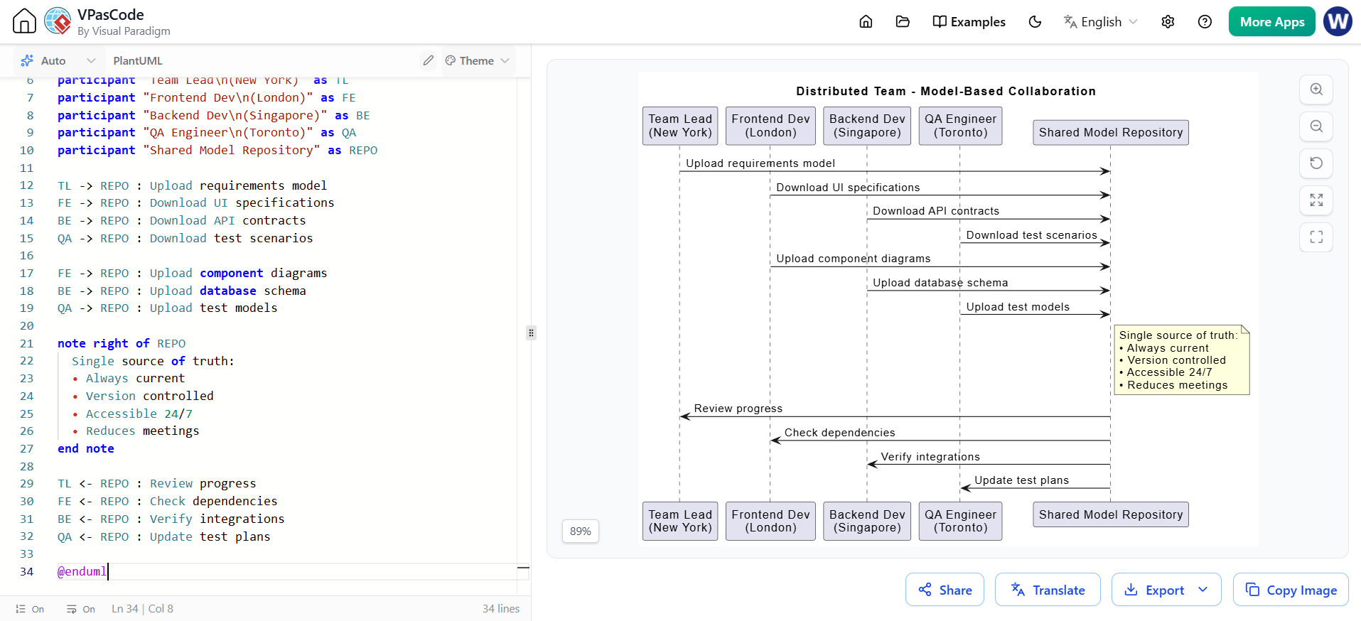
@startuml
skinparam backgroundColor #FFFFFF

title "Distributed Team - Model-Based Collaboration"

participant "Team Lead\n(New York)" as TL
participant "Frontend Dev\n(London)" as FE
participant "Backend Dev\n(Singapore)" as BE
participant "QA Engineer\n(Toronto)" as QA
participant "Shared Model Repository" as REPO

TL -> REPO : Upload requirements model
FE -> REPO : Download UI specifications
BE -> REPO : Download API contracts
QA -> REPO : Download test scenarios

FE -> REPO : Upload component diagrams
BE -> REPO : Upload database schema
QA -> REPO : Upload test models

note right of REPO
  Single source of truth:
  • Always current
  • Version controlled
  • Accessible 24/7
  • Reduces meetings
  • Asynchronous collaboration
end note

TL <- REPO : Review progress
FE <- REPO : Check dependencies
BE <- REPO : Verify integrations
QA <- REPO : Update test plans

@enduml
Example 3: Regulatory Compliance Communication
Scenario: Healthcare Software Development
Models for Compliance:
Data Flow Diagrams: Show how patient data moves through the system (HIPAA compliance)
Security Architecture Models: Demonstrate encryption and access controls
Audit Trail Models: Illustrate how system logs all access and changes
Risk Assessment Models: Document identified risks and mitigation strategies
Communication Benefits:
Regulators can review models instead of code
Auditors can verify compliance visually
Legal teams can assess liability from diagrams
Management can understand compliance status
Example 4: Agile Development Communication
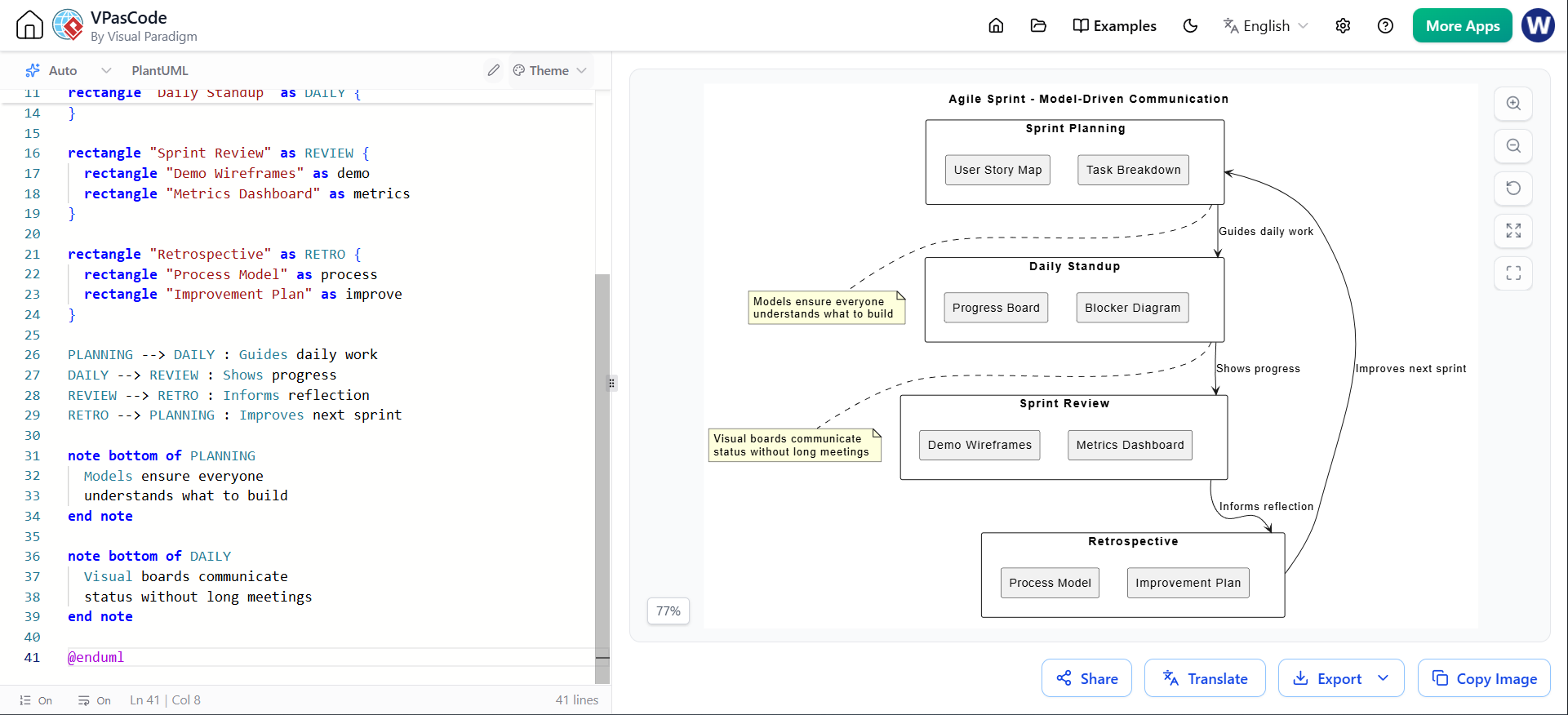
@startuml
skinparam backgroundColor #FFFFFF

title "Agile Sprint - Model-Driven Communication"

rectangle "Sprint Planning" as PLANNING {
  rectangle "User Story Map" as stories
  rectangle "Task Breakdown" as tasks
}

rectangle "Daily Standup" as DAILY {
  rectangle "Progress Board" as board
  rectangle "Blocker Diagram" as blockers
}

rectangle "Sprint Review" as REVIEW {
  rectangle "Demo Wireframes" as demo
  rectangle "Metrics Dashboard" as metrics
}

rectangle "Retrospective" as RETRO {
  rectangle "Process Model" as process
  rectangle "Improvement Plan" as improve
}

PLANNING --> DAILY : Guides daily work
DAILY --> REVIEW : Shows progress
REVIEW --> RETRO : Informs reflection
RETRO --> PLANNING : Improves next sprint

note bottom of PLANNING
  Models ensure everyone
  understands what to build
end note

note bottom of DAILY
  Visual boards communicate
  status without long meetings
end note

note bottom of REVIEW
  Demos with models show
  working software clearly
end note

@enduml
Key Takeaway: Models serve as a universal language that transcends individual perspectives, enabling diverse stakeholders to collaborate effectively with shared understanding.
Organizational Mechanisms
Models employ several powerful mechanisms to organize complex information, making it manageable and comprehensible. These mechanisms provide structure and clarity to otherwise overwhelming complexity.
Key Mechanisms:
Perspectives: Different "lenses" for viewing the system
Levels of Abstraction: Scaling from system-wide to component-level views
Traceability: Connecting requirements to implementation
Examples:
Example 1: Multiple Perspectives
Conceptualization vs. Implementation Perspective:
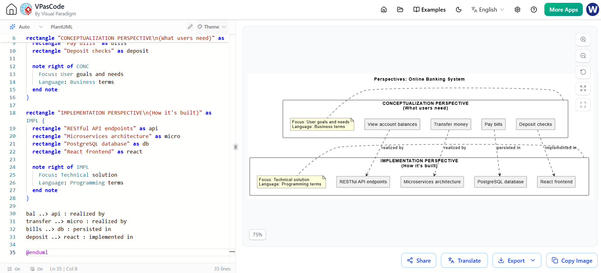
@startuml
skinparam backgroundColor #FFFFFF

title "Perspectives: Online Banking System"

rectangle "CONCEPTUALIZATION PERSPECTIVE\n(What users need)" as CONC {
  rectangle "View account balances" as bal
  rectangle "Transfer money" as transfer
  rectangle "Pay bills" as bills
  rectangle "Deposit checks" as deposit

  note right of CONC
    Focus: User goals and needs
    Language: Business terms
    Concerns: Functionality,
    usability, value
  end note
}

rectangle "IMPLEMENTATION PERSPECTIVE\n(How it's built)" as IMPL {
  rectangle "RESTful API endpoints" as api
  rectangle "Microservices architecture" as micro
  rectangle "PostgreSQL database" as db
  rectangle "React frontend" as react
  rectangle "OAuth 2.0 authentication" as oauth

  note right of IMPL
    Focus: Technical solution
    Language: Programming terms
    Concerns: Performance,
    scalability, security
  end note
}

bal ..> api : realized by
transfer ..> micro : realized by
bills ..> db : persisted in
deposit ..> react : implemented in
oauth ..> oauth : secured by

note bottom of CONC
  Stakeholders: Customers,
  business analysts, product owners
end note

note bottom of IMPL
  Stakeholders: Developers,
  architects, DevOps engineers
end note

@enduml
Example 2: System, Subsystem, and Primitive Levels
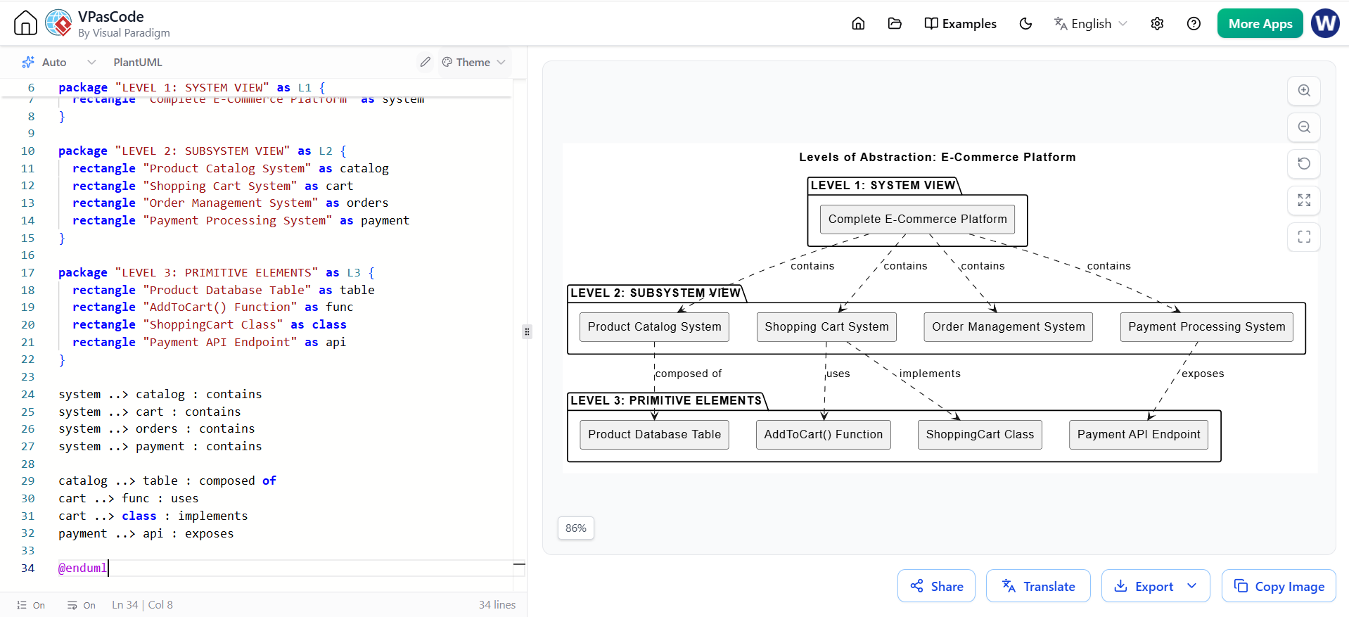
@startuml
skinparam backgroundColor #FFFFFF

title "Levels of Abstraction: E-Commerce Platform"

package "LEVEL 1: SYSTEM VIEW" as L1 {
  rectangle "Complete E-Commerce Platform" as system
}

package "LEVEL 2: SUBSYSTEM VIEW" as L2 {
  rectangle "Product Catalog System" as catalog
  rectangle "Shopping Cart System" as cart
  rectangle "Order Management System" as orders
  rectangle "Payment Processing System" as payment
  rectangle "User Management System" as users
}

package "LEVEL 3: PRIMITIVE ELEMENTS" as L3 {
  rectangle "Product Database Table" as table
  rectangle "AddToCart() Function" as func
  rectangle "ShoppingCart Class" as class
  rectangle "Payment API Endpoint" as api
  rectangle "User Session Cookie" as cookie
}

system ..> catalog : contains
system ..> cart : contains
system ..> orders : contains
system ..> payment : contains
system ..> users : contains

catalog ..> table : composed of
cart ..> func : uses
cart ..> class : implements
payment ..> api : exposes
users ..> cookie : manages

note right of L1
  Audience: Executives,
  stakeholders
  Detail: Minimal
  Purpose: Strategic planning
end note

note right of L2
  Audience: Architects,
  team leads
  Detail: Moderate
  Purpose: System design
end note

note right of L3
  Audience: Developers,
  testers
  Detail: Extensive
  Purpose: Implementation
end note

@enduml
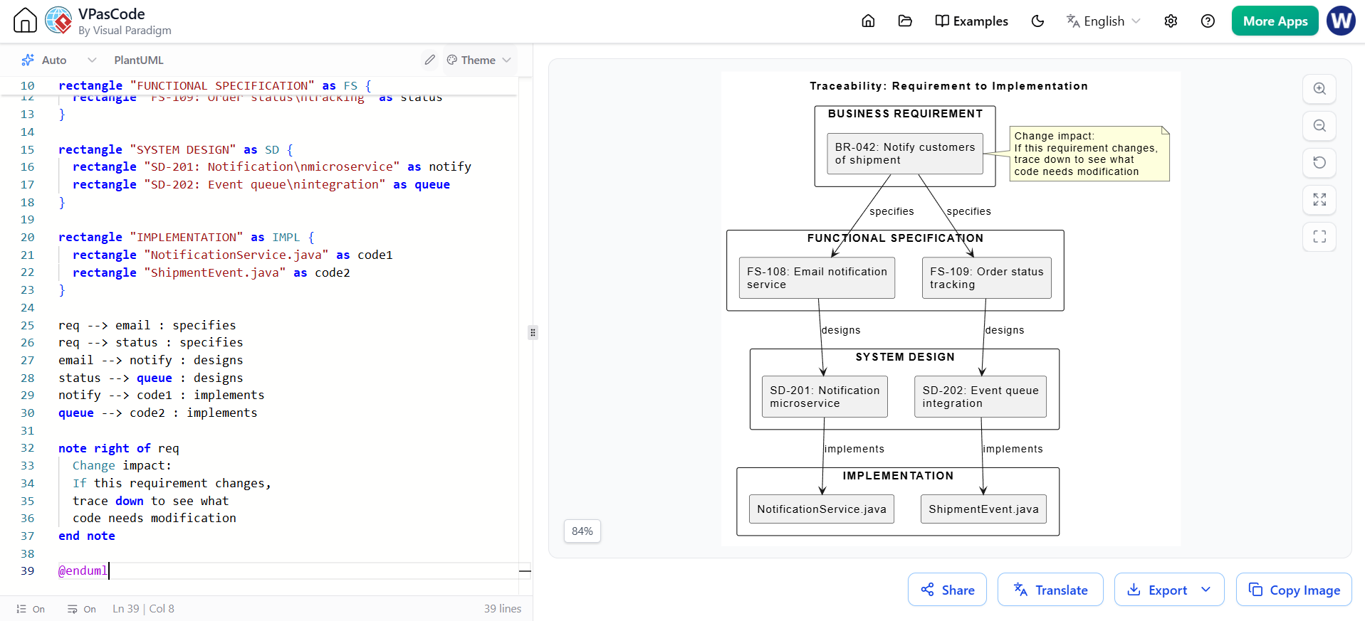
Example 3: Traceability in Action
Scenario: Change Management
A business stakeholder requests: "Customers should receive email notifications when their order ships."
Traceability Chain:
@startuml
skinparam backgroundColor #FFFFFF

title "Traceability: Requirement to Implementation"

rectangle "BUSINESS REQUIREMENT" as BR {
  rectangle "BR-042: Notify customers\nof shipment" as req
}

rectangle "FUNCTIONAL SPECIFICATION" as FS {
  rectangle "FS-108: Email notification\nservice" as email
  rectangle "FS-109: Order status\ntracking" as status
}

rectangle "SYSTEM DESIGN" as SD {
  rectangle "SD-201: Notification\nmicroservice" as notify
  rectangle "SD-202: Event queue\nintegration" as queue
}

rectangle "IMPLEMENTATION" as IMPL {
  rectangle "NotificationService.java" as code1
  rectangle "ShipmentEvent.java" as code2
  rectangle "EmailTemplate.html" as code3
}

rectangle "TEST CASES" as TEST {
  rectangle "TC-501: Verify email\non shipment" as test1
  rectangle "TC-502: Verify email\ncontent" as test2
}

req --> email : specifies
req --> status : specifies
email --> notify : designs
status --> queue : designs
notify --> code1 : implements
queue --> code2 : implements
email --> code3 : implements
code1 --> test1 : validates
code3 --> test2 : validates

note right of req
  Change impact:
  If this requirement changes,
  trace down to see what
  code needs modification
end note

note left of code1
  Change propagation:
  If this code changes,
  trace up to see what
  requirements are affected
end note

@enduml
Traceability Benefits:
Impact Analysis: When a requirement changes, you can trace down to see exactly which components, code, and tests need modification
Compliance Verification: Prove that every requirement has been implemented and tested
Debugging: When a bug is found, trace up to understand which requirements are affected
Project Management: Track progress from requirements through to completion
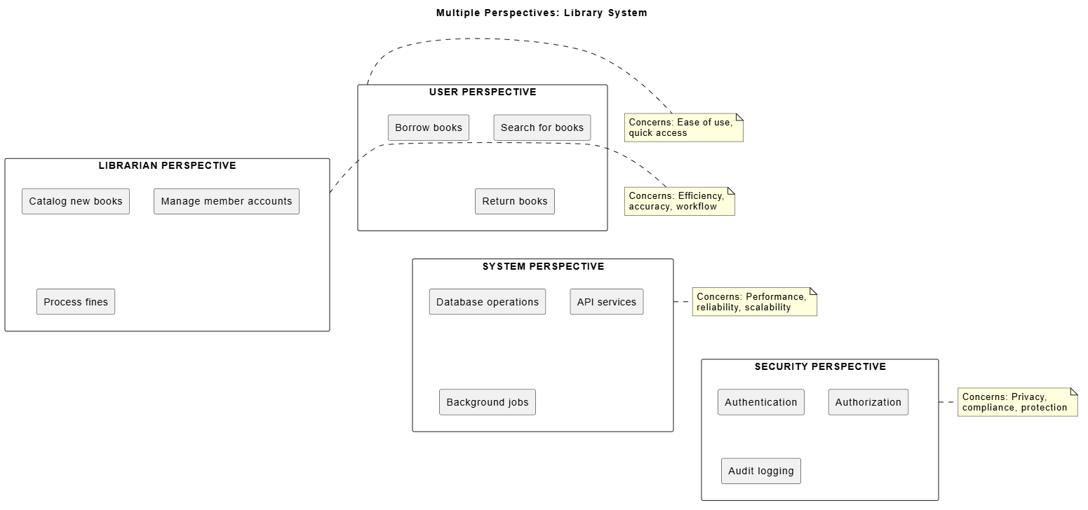
Example 4: Perspective Switching - Library Management System
@startuml
skinparam backgroundColor #FFFFFF

title "Multiple Perspectives: Library System"

rectangle "USER PERSPECTIVE" as USER {
  rectangle "Search for books" as search
  rectangle "Borrow books" as borrow
  rectangle "Return books" as return
  rectangle "Reserve books" as reserve
}

rectangle "LIBRARIAN PERSPECTIVE" as LIB {
  rectangle "Catalog new books" as catalog
  rectangle "Manage member accounts" as members
  rectangle "Process fines" as fines
  rectangle "Generate reports" as reports
}

rectangle "SYSTEM PERSPECTIVE" as SYS {
  rectangle "Database operations" as db
  rectangle "API services" as api
  rectangle "Background jobs" as jobs
  rectangle "Cache management" as cache
}

rectangle "SECURITY PERSPECTIVE" as SEC {
  rectangle "Authentication" as auth
  rectangle "Authorization" as authz
  rectangle "Audit logging" as audit
  rectangle "Data encryption" as encrypt
}

USER -[hidden]-> LIB
LIB -[hidden]-> SYS
SYS -[hidden]-> SEC

note right of USER
  Concerns: Ease of use,
  quick access, mobile friendly
end note

note right of LIB
  Concerns: Efficiency,
  accuracy, workflow
end note

note right of SYS
  Concerns: Performance,
  reliability, scalability
end note

note right of SEC
  Concerns: Privacy,
  compliance, protection
end note

@enduml
Example 5: Comprehensive Traceability Matrix
Real-World Application: Medical Device Software
| Requirement ID | Description | Design Component | Code Module | Test Case | Status |
|---|---|---|---|---|---|
| REQ-001 | Device must alarm when heart rate < 40 bpm | Alarm System v2.1 | alarm_monitor.c | TC-101 | Passed |
| REQ-002 | Battery life indicator must update every 5 min | Power Management v1.3 | battery_status.c | TC-205 | Passed |
| REQ-003 | Data must be encrypted at rest | Security Module v3.0 | encryption.c | TC-312 | In Progress |
Key Takeaway: Organizational mechanisms like perspectives, abstraction levels, and traceability transform chaotic complexity into structured, manageable information that can be effectively understood and controlled.
Managing complexity in systems development is not optional—it's essential for success. As we've explored throughout this guide, models serve as the primary tool for taming complexity and preventing chaos in development projects. Through the five key mechanisms we've examined, models provide powerful capabilities that every developer should master:
1. Abstraction allows us to focus on what matters while hiding irrelevant details, enabling us to work at the appropriate level of detail for each task.
2. Blueprints transform abstract ideas into concrete plans, providing visualization, specification, and construction guidance that bridge the gap between concept and reality.
3. Early Validation enables us to test, verify, and refine our designs before committing expensive resources, dramatically reducing risk and cost.
4. Communication creates a common language that aligns diverse stakeholders, reduces misunderstandings, and enables effective collaboration across teams and disciplines.
5. Organizational Mechanisms provide structure through perspectives, abstraction levels, and traceability, making complex information manageable and comprehensible.
For beginners entering the field of systems development, understanding and applying these modeling concepts is crucial. Start by practicing abstraction—learn to identify essential details and ignore the rest. Create simple models before writing code. Use diagrams to communicate your ideas. Trace requirements through to implementation. These habits will serve you throughout your career.
Remember: Complexity is inevitable, but chaos is optional. With models as your tool, you can navigate even the most complex systems with confidence, clarity, and control. The investment you make in learning to model effectively will pay dividends in every project you undertake, enabling you to build better systems, collaborate more effectively, and deliver greater value to your stakeholders.
As you continue your journey in systems development, keep modeling at the forefront of your practice. Let models be your guide through complexity, your bridge to understanding, and your foundation for building exceptional systems.

