
Translating complex business requirements into a robust, scalable software architecture is one of the most critical challenges in software engineering. If designers jump straight into coding or database schemas, they risk creating rigid systems that fail to adapt to changing business needs. To prevent this, UML (Unified Modeling Language) introduces the concept of a conceptual solution—an abstract, ideal representation of a system that focuses purely on what the system must do, completely disconnected from how it will be implemented.
At the heart of this conceptual solution is the Boundary-Control-Entity (BCE) pattern, a foundational technique used in UML Robustness Analysis. By "objectifying" a system into these three distinct conceptual elements, architects can clearly define system requirements, map out interactions, and establish a solid blueprint before transitioning into the physical design phase.
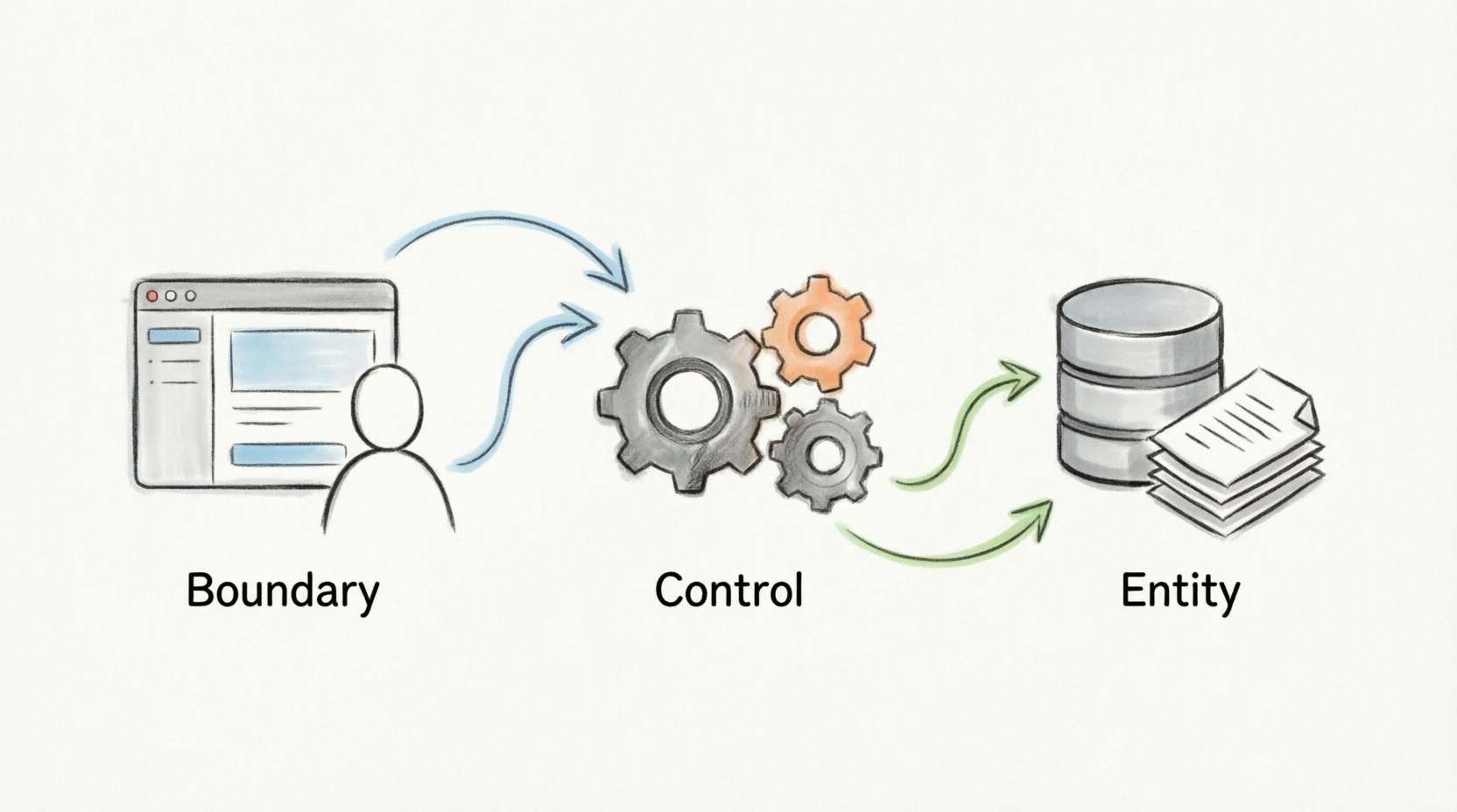
This guide provides a comprehensive overview of the Boundary, Control, and Entity concepts, illustrating how they work together to bridge the gap between raw business requirements and concrete software design.
The BCE pattern categorizes every conceptual element in a system into one of three roles. This separation of concerns ensures that user interfaces, business logic, and data management remain decoupled.
Boundary concepts represent the interface between the system and the outside world. They are the "senses" and "voice" of the system.
Definition: Abstractions representing the means for input or output through which actors (human users or external systems) interact with the system.
Primary Responsibility: Coordinating the interaction between the system and its actors. They translate external events into internal system messages and vice versa.
Notation: Represented as a class stereotyped with the «boundary» keyword. (In specialized UML tools, this is drawn as a circle with a vertical line connected via a horizontal line on its left side).
Navigation Rules:
An actor may have a navigable relationship to a boundary class.
A boundary class may navigate to an actor (to send a response), or to boundary, control, or entity classes.
Examples of Boundary Concepts:
LoginScreenUI: A graphical interface for a human user to enter credentials.
PaymentGatewayAPI: A system-to-system interface that receives credit card payloads from an external payment processor.
TemperatureSensorReceiver: A boundary class that ingests raw data from an IoT hardware sensor.
EmailNotificationDispatcher: A boundary class that formats and sends outbound emails to users.
Control concepts act as the "brain" or coordinator for specific tasks, processes, or use cases.
Definition: Abstractions representing the processing by which input data is transformed into output data.
Primary Responsibility: Coordinating the processing provided by the system. Crucially, the control concept does not perform the core business logic itself; instead, it manages, sequences, and delegates responsibility to other elements.
Notation: Represented as a class stereotyped with the «control» keyword. (Icon: a circle with a small counterclockwise arrow at the top).
Navigation Rules: A control class may have a navigable relationship to boundary, control, or entity classes.
Examples of Control Concepts:
CheckoutProcessController: Orchestrates the steps of an e-commerce checkout (validating cart, calculating tax, processing payment).
AuthenticationManager: Coordinates the verification of a user by delegating to the UserCredentials entity and the LoginScreenUI boundary.
InventoryUpdateCoordinator: Manages the workflow of updating stock levels across multiple warehouses when an order is placed.
FlightBookingHandler: Sequences the reservation process, ensuring seats are locked, payments are cleared, and tickets are issued in the correct order.
Entity concepts are the passive holders of the system's knowledge. They represent the "memory" of the system.
Definition: Abstractions representing the passive data and information that is input, processed, and output by the system.
Origin: They are typically derived directly from the business domain model or context modeling discipline.
Primary Responsibility: Storing, managing, and providing access to data and information.
Notation: Represented as a class stereotyped with the «entity» keyword. (Icon: a circle with a horizontal line attached to the bottom).
Navigation Rules: An entity class may only navigate to other entity classes. Because entities are passive, they do not initiate interactions with boundaries or controls on their own.
Examples of Entity Concepts:
Customer: Holds personal details, shipping addresses, and account status.
Order: Contains order date, total amount, and a collection of OrderItem entities.
BankAccount: Stores account numbers, current balances, and transaction histories.
ProductCatalogItem: Holds SKU, price, description, and weight.
Below are PlantUML examples demonstrating how these concepts interact in both structural (Class) and behavioral (Sequence) models.
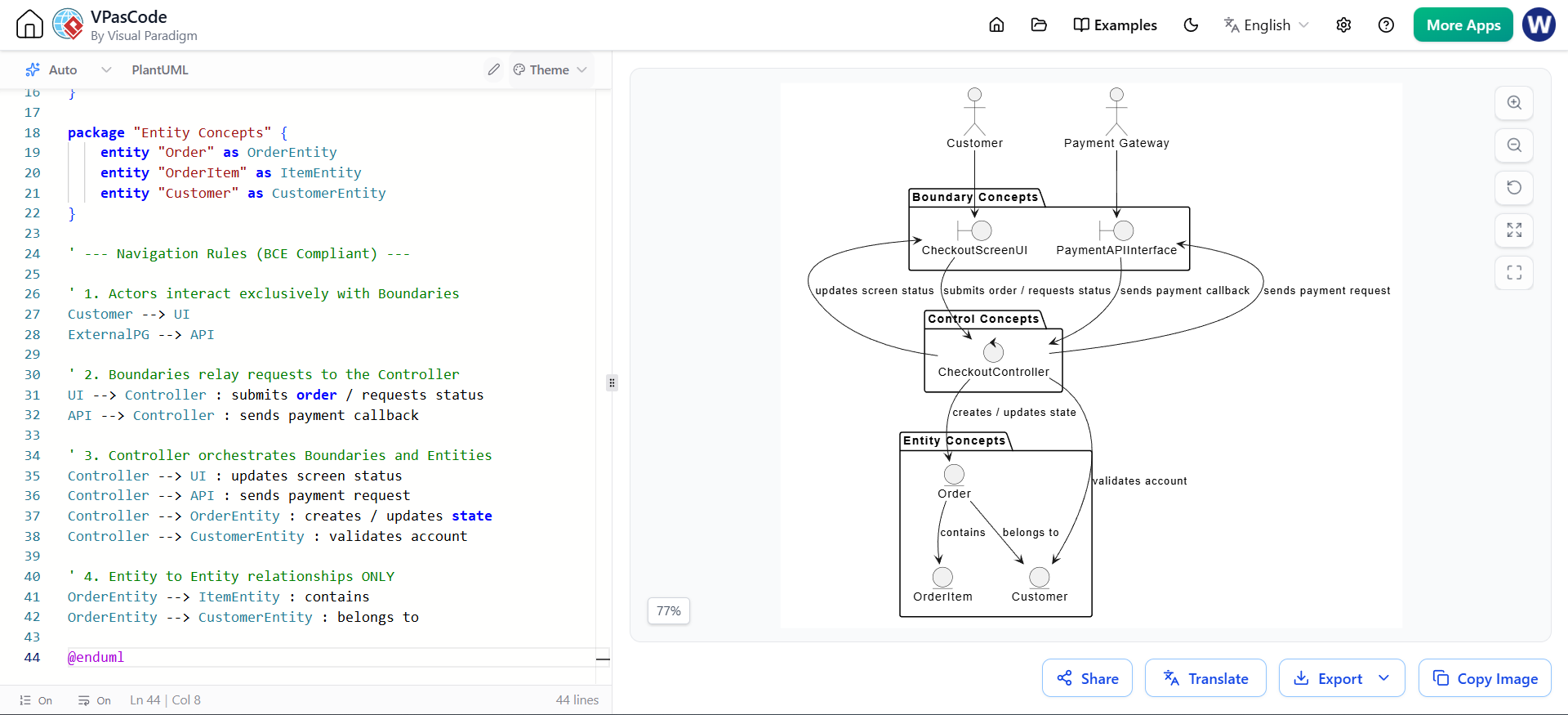
This diagram illustrates the structural relationships and strict navigation rules between the BCE elements. Notice how the Order entity only navigates to the OrderItem entity, strictly adhering to the rules.
@startuml
skinparam monochrome true

' --- Actors ---
actor Customer
actor "Payment Gateway" as ExternalPG

' --- BCE Elements ---
package "Boundary Concepts" {
    boundary "CheckoutScreenUI" as UI
    boundary "PaymentAPIInterface" as API
}

package "Control Concepts" {
    control "CheckoutController" as Controller
}

package "Entity Concepts" {
    entity "Order" as OrderEntity
    entity "OrderItem" as ItemEntity
    entity "Customer" as CustomerEntity
}

' --- Navigation Rules (BCE Compliant) ---

' 1. Actors interact exclusively with Boundaries
Customer --> UI
ExternalPG --> API

' 2. Boundaries relay requests to the Controller
UI --> Controller : submits order / requests status
API --> Controller : sends payment callback

' 3. Controller orchestrates Boundaries and Entities
Controller --> UI : updates screen status
Controller --> API : sends payment request
Controller --> OrderEntity : creates / updates state
Controller --> CustomerEntity : validates account

' 4. Entity to Entity relationships ONLY
OrderEntity --> ItemEntity : contains
OrderEntity --> CustomerEntity : belongs to

@enduml
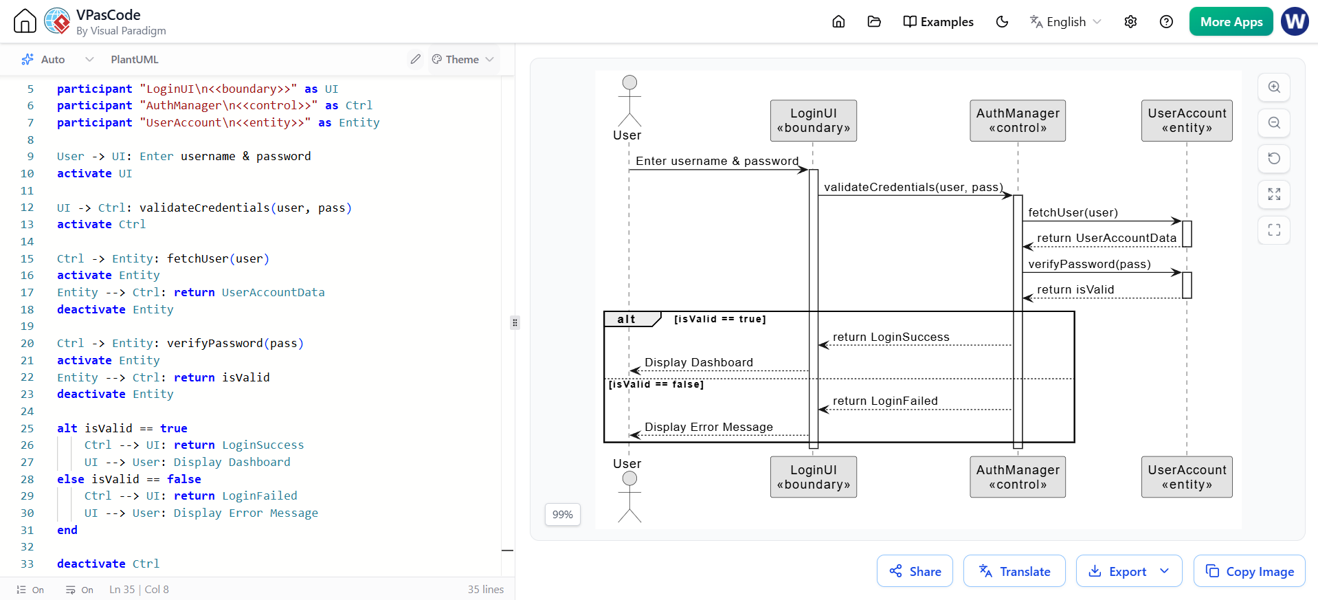
Sequence diagrams are where the BCE pattern truly shines. It visualizes the flow of a specific use case, proving that the conceptual solution actually works.
@startuml
skinparam monochrome true

actor User
participant "LoginUI\n<<boundary>>" as UI
participant "AuthManager\n<<control>>" as Ctrl
participant "UserAccount\n<<entity>>" as Entity

User -> UI: Enter username & password
activate UI

UI -> Ctrl: validateCredentials(user, pass)
activate Ctrl

Ctrl -> Entity: fetchUser(user)
activate Entity
Entity --> Ctrl: return UserAccountData
deactivate Entity

Ctrl -> Entity: verifyPassword(pass)
activate Entity
Entity --> Ctrl: return isValid
deactivate Entity

alt isValid == true
    Ctrl --> UI: return LoginSuccess
    UI --> User: Display Dashboard
else isValid == false
    Ctrl --> UI: return LoginFailed
    UI --> User: Display Error Message
end

deactivate Ctrl
deactivate UI
@enduml
Conceptual elements are not static; they are applied throughout the system's "containment hierarchy" and evolve as the model becomes more granular. Understanding this evolution is key to scaling a system from a high-level vision to detailed code.
| Level of Abstraction | Boundary Concepts evolve into... | Control Concepts evolve into... | Entity Concepts evolve into... |
|---|---|---|---|
| System Level | System interfaces or interface operations. | Active system parts (subsystems/classes) that initiate control. | Passive system parts (packages/classes). |
| Subsystem Level | Subsystem interfaces or operations. | Active subsystem parts (enclosed subsystems/classes). | Passive subsystem parts. |
| Class Level | Class operation specifications (e.g., UI methods). | Class operation implementations or methods (e.g., service logic). | Class attributes (e.g., database columns/fields). |
Example of Evolution: At the System Level, a Boundary might be the "Payment Gateway Interface". At the Class Level, it evolves into specific class operations like processCreditCard() and formatReceipt().
Within the UML Roadmap, BCE elements are introduced during the Analysis phase and serve as the bridge to the Design phase.
Establishing a Conceptual Solution: Using BCE allows designers to focus purely on the requirements ("what" the system should do) without being hindered by implementation details, technology stacks, or database constraints ("how" it will be built).
Fitness Criteria: This conceptual solution establishes "fit criteria"—objective rules by which a proposed solution can be judged for suitability, performance, and completeness.
Transition to Design: During the Design phase, these conceptual elements are mapped to "candidate elements" to identify actual elements. A single conceptual element might remain a single class, be split into multiple classes, or expand into an entire package or subsystem based on real-world constraints like cohesion, coupling, and performance.
Validation: Finally, designers validate that the actual classes (e.g., specific Java, C#, or C++ classes) fully support the structure and behavior required by their original conceptual elements. If the actual code fails to support the conceptual model, the design must be refactored.
The Boundary-Control-Entity (BCE) pattern is an indispensable tool in the UML modeler's toolkit. By strictly separating the system's interactions (Boundary), its coordination logic (Control), and its data (Entity), architects can create robust, implementation-agnostic conceptual solutions. This separation not only makes complex systems easier to understand and communicate but also ensures that the final software design remains closely aligned with the original business requirements.
To effectively capture, visualize, and manage these conceptual models throughout the UML Roadmap, utilizing professional modeling software is highly recommended. Tools like Visual Paradigm provide comprehensive support for the BCE pattern, offering intuitive drag-and-drop interfaces for Boundary, Control, and Entity stereotypes, automated diagram generation, and seamless transitions from Analysis to Design. By leveraging such tooling, development teams can ensure their conceptual solutions are accurately documented, easily validated, and perfectly positioned for successful implementation.

