
In the complex landscape of software engineering, Unified Modeling Language (UML) serves as the universal visual language for blueprinting systems. However, simply knowing UML diagram types is not enough; practitioners need a structured methodology to know when and how to apply them. This is where the UML Roadmap comes into play.
The UML Roadmap organizes the modeling process into a logical progression, guiding teams from the initial understanding of a business problem to the logical design of a solution, and finally to its physical deployment. By structuring the development lifecycle into three distinct perspectives—Conceptualization, Specification, and Implementation—the roadmap ensures that no requirement is lost in translation and that the final physical system perfectly aligns with the original business needs.
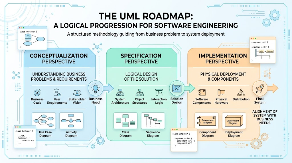
This guide provides a comprehensive exploration of the UML Roadmap, detailing its key concepts, providing real-world examples, and illustrating the modeling process with PlantUML diagrams.
The Conceptualization perspective is the starting point of the UML Roadmap. It is strictly concerned with the problem domain and views the system conceptually as a "black box". At this stage, we do not care about how the system will be built internally; we only care about what the system must do and who will interact with it.
Actors: External entities (users, external systems) that interact with the system.
Examples: A "Bank Customer" withdrawing cash, an "Inventory Clerk" scanning items, or an external "Payment Gateway API".
Use Cases: Specific goals or functionalities the system provides to the actors.
Examples: "Process Refund", "Generate Monthly Report", "Authenticate User".
System Boundary: The conceptual line separating the system being built from the external environment.
Examples: The "E-Commerce Platform" boundary enclosing the "Checkout" use case, but excluding the "Shipping Provider" actor.
This diagram captures the requirements and functionality from the user's point of view.
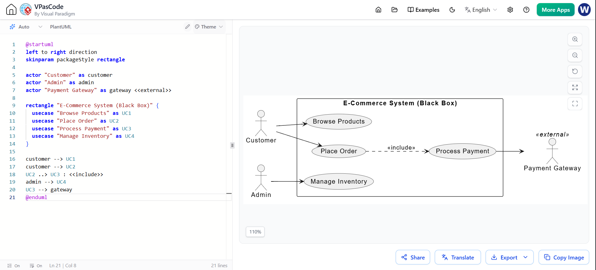
@startuml
left to right direction
skinparam packageStyle rectangle

actor "Customer" as customer
actor "Admin" as admin
actor "Payment Gateway" as gateway <<external>>

rectangle "E-Commerce System (Black Box)" {
  usecase "Browse Products" as UC1
  usecase "Place Order" as UC2
  usecase "Process Payment" as UC3
  usecase "Manage Inventory" as UC4
}

customer --> UC1
customer --> UC2
UC2 ..> UC3 : <<include>>
admin --> UC4
UC3 --> gateway
@enduml
The Specification perspective bridges the gap between the problem and the physical solution. It views the system logically as a "white box", meaning we can now "look inside" to see the internal workings. The focus shifts from what the system does to how it logically achieves its goals through collaborating elements.
Structural Modeling (Classes & Objects): Identifying the logical data and business rules.
Examples: An Order class containing attributes like orderDate and methods like calculateTotal(). An Invoice object linked to a Customer.
Behavioral Modeling (Interactions & States): Defining how objects collaborate over time and how they change states.
Examples (Sequence): The step-by-step message passing between UserController, AuthService, and Database during a login.
Examples (State Machine): The lifecycle of an Order transitioning from Pending -> Paid -> Shipped -> Delivered.
A. Structural Modeling (Class Diagram)
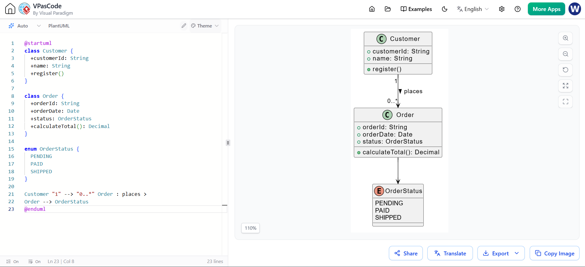
@startuml
class Customer {
  +customerId: String
  +name: String
  +register()
}

class Order {
  +orderId: String
  +orderDate: Date
  +status: OrderStatus
  +calculateTotal(): Decimal
}

enum OrderStatus {
  PENDING
  PAID
  SHIPPED
}

Customer "1" --> "0..*" Order : places >
Order --> OrderStatus
@enduml
B. Behavioral Modeling (Sequence Diagram)
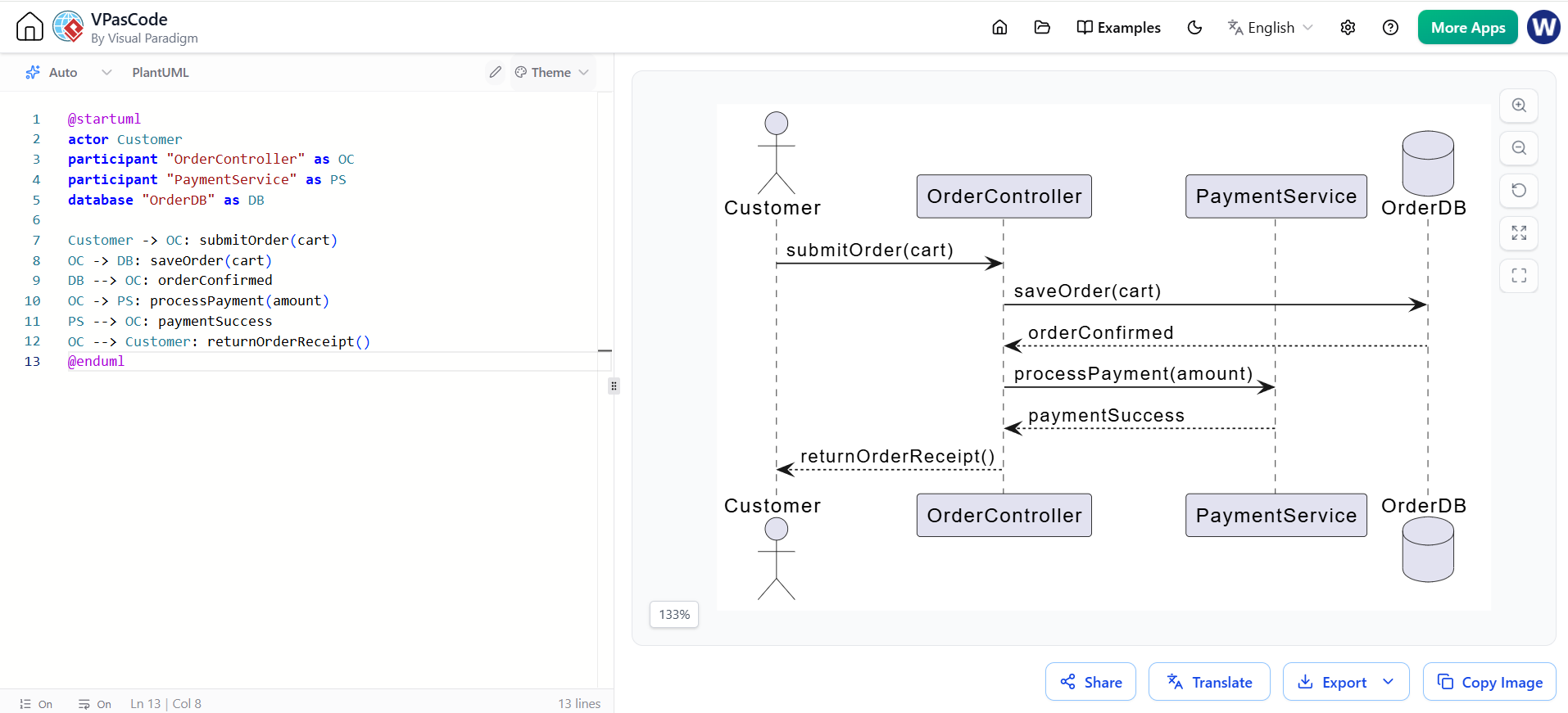
@startuml
actor Customer
participant "OrderController" as OC
participant "PaymentService" as PS
database "OrderDB" as DB

Customer -> OC: submitOrder(cart)
OC -> DB: saveOrder(cart)
DB --> OC: orderConfirmed
OC -> PS: processPayment(amount)
PS --> OC: paymentSuccess
OC --> Customer: returnOrderReceipt()
@enduml
Also known as the realization perspective, this final stage is concerned with the final solution and views the system physically as a "black box". While the specification perspective looked at logical "white box" internals, the implementation perspective looks at how those logical elements are packaged into executable software components and deployed onto physical hardware or cloud infrastructure.
Components: Modular, physical parts of the system that encapsulate logical classes.
Examples: A UserManagement.jar file, a React_Frontend module, or a Legacy_Billing_DLL.
Nodes & Deployment: The physical hardware or execution environments where components run.
Examples: An "AWS EC2 Instance", a "Docker Container", an "iOS Mobile Device", or an "Oracle Database Server".
Artifacts: The actual physical files generated during the build process.
Examples: app.war, main.exe, schema.sql.
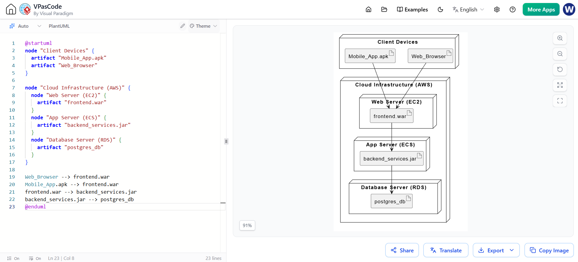
@startuml
node "Client Devices" {
  artifact "Mobile_App.apk"
  artifact "Web_Browser"
}

node "Cloud Infrastructure (AWS)" {
  node "Web Server (EC2)" {
    artifact "frontend.war"
  }
  node "App Server (ECS)" {
    artifact "backend_services.jar"
  }
  node "Database Server (RDS)" {
    artifact "postgres_db"
  }
}

Web_Browser --> frontend.war
Mobile_App.apk --> frontend.war
frontend.war --> backend_services.jar
backend_services.jar --> postgres_db
@enduml
A critical feature of the UML Roadmap is Traceability. Because the same core concepts evolve through the three perspectives, the roadmap uses traceability relationships (represented as dependencies stereotyped with «trace») to connect related elements.
If a business stakeholder changes a requirement in the Conceptualization phase (e.g., "Users must now use Two-Factor Authentication"), traceability allows the architect to instantly see which logical classes in the Specification phase need updating (e.g., AuthService), and which physical components in the Implementation phase are affected (e.g., the SecurityModule.dll).
Traceability PlantUML Example:
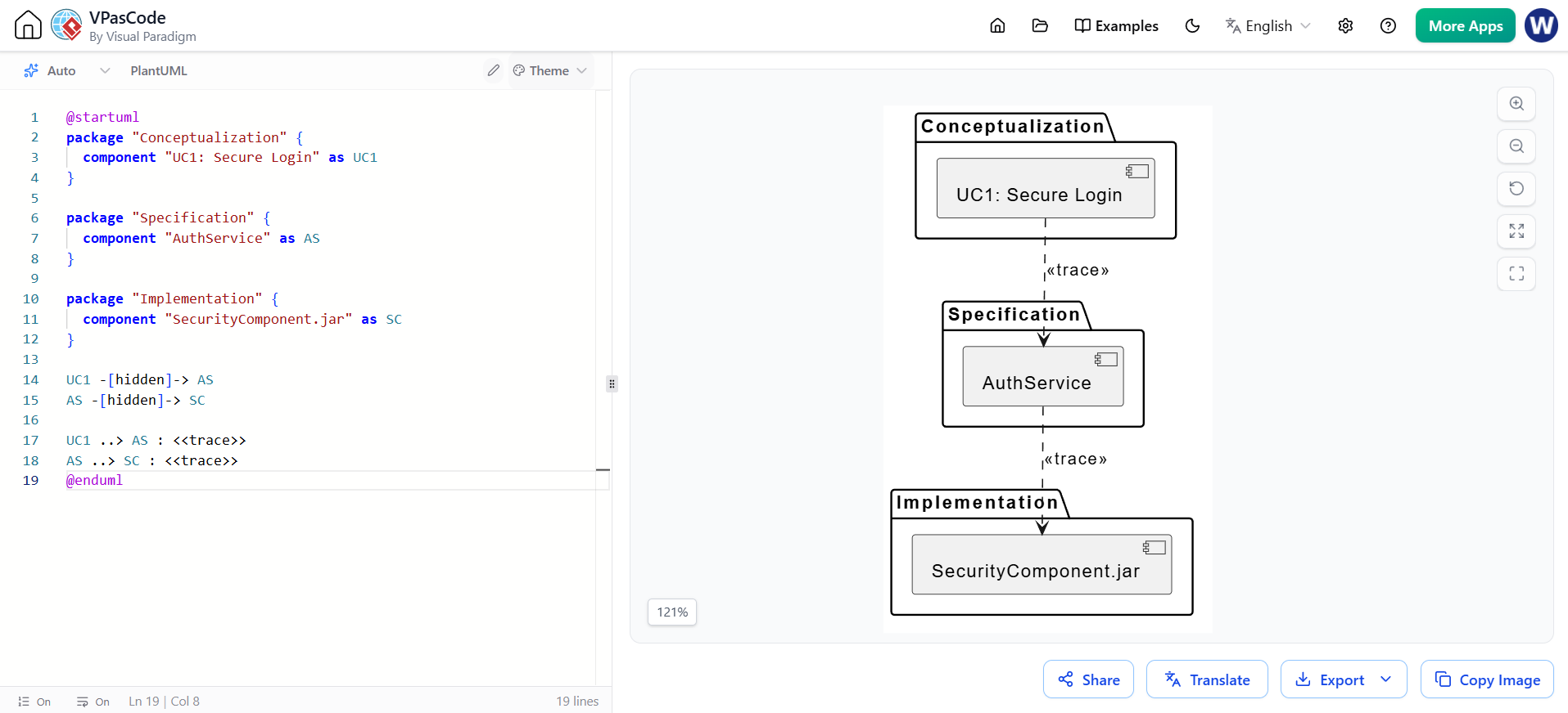
@startuml
package "Conceptualization" {
  component "UC1: Secure Login" as UC1
}

package "Specification" {
  component "AuthService" as AS
}

package "Implementation" {
  component "SecurityComponent.jar" as SC
}

UC1 -[hidden]-> AS
AS -[hidden]-> SC

UC1 ..> AS : <>
AS ..> SC : <>
@enduml
The true power of the UML Roadmap is realized when the 3 Perspectives are crossed with 3 Levels of Abstraction (System, Subsystem, and Class). This creates a matrix of nine distinct models that guide development from the highest level down to the code level:
| Abstraction Level | Conceptualization (Problem / Black Box) | Specification (Logical / White Box) | Implementation (Physical / Black Box) |
|---|---|---|---|
| System | System Use Cases: Overall system goals and external actors. | System Architecture: High-level logical subsystems and their interactions. | System Deployment: Overall physical topology, networks, and major nodes. |
| Subsystem | Subsystem Use Cases: Specific functionalities of a major module. | Subsystem Structure/Behavior: Detailed classes, states, and interactions within the module. | Subsystem Components: Packaging of the module into specific files/libraries. |
| Class | Class Use Cases: (Rarely used) Specific goals tied to a single domain object. | Class Structure/Behavior: Detailed attributes, methods, and state machines of the class. | Class Implementation: How the class is realized in specific programming language artifacts. |
The UML Roadmap is an indispensable framework for managing the complexity of software development. By strictly separating the modeling process into Conceptualization (understanding the problem), Specification (designing the logical solution), and Implementation (realizing the physical solution), teams can maintain clarity and focus at every stage of the lifecycle. Furthermore, the integration of traceability across the 9-model grid ensures that business requirements are never lost, allowing for precise impact analysis when changes occur.
To effectively execute the UML Roadmap, teams require robust tooling that supports multi-perspective modeling, automated traceability, and code generation. Visual Paradigm is highly recommended for this purpose. As a comprehensive UML tool, Visual Paradigm natively supports the UML Roadmap framework, allowing architects to seamlessly transition between the 9 models, manage «trace» dependencies visually, and ensure that the physical deployment diagrams perfectly reflect the logical specifications and original business requirements.

