
In the realm of software engineering and system design, visualizing how components interact over time is crucial for building robust applications. Enter the Sequence Diagram, a fundamental interaction diagram in the Unified Modeling Language (UML) 2.0. Unlike other diagrams that focus on static structures or spatial relationships, sequence diagrams focus specifically on the time-ordering of messages exchanged between objects during system execution.
Whether you are a system architect, a software developer, or a business analyst, understanding how to read and create sequence diagrams is essential for translating functional requirements into actionable design. This comprehensive guide will walk you through the key concepts, advanced features, and practical applications of UML 2.0 sequence diagrams, complete with PlantUML code examples to help you visualize the concepts.
To effectively read and draw sequence diagrams, you must understand the standard UML 2.0 notation. The diagram is read from top to bottom, representing the flow of time.
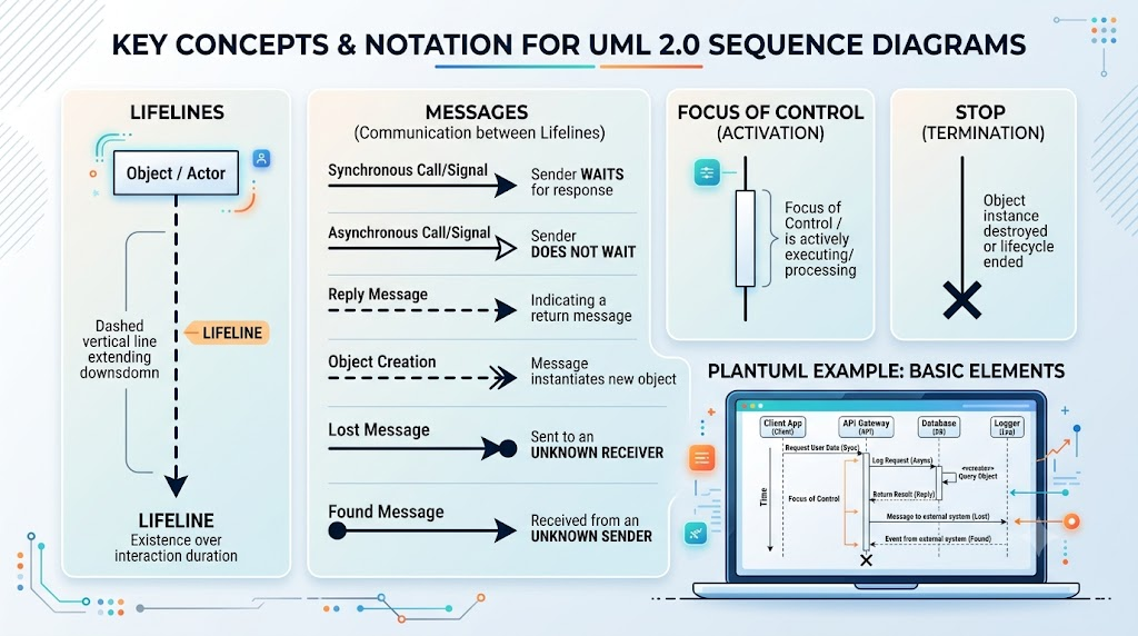
Lifelines represent the participation of an object (or actor) in an interaction. They are depicted as a dashed vertical line extending downward from the top of the object's rectangular box. The lifeline represents the existence of the object over the duration of the interaction.
Communication between objects occurs via messages sent between lifelines. UML 2.0 defines specific arrow notations to indicate the type of message being sent:
Also known as an execution occurrence, the focus of control is a thin rectangle placed on a lifeline. It explicitly indicates the time period during which an object is actively executing a behavior or processing a message.
The termination of an object's instance is marked by an "X" at the bottom of its lifeline, indicating that the object has been destroyed or its lifecycle has ended.
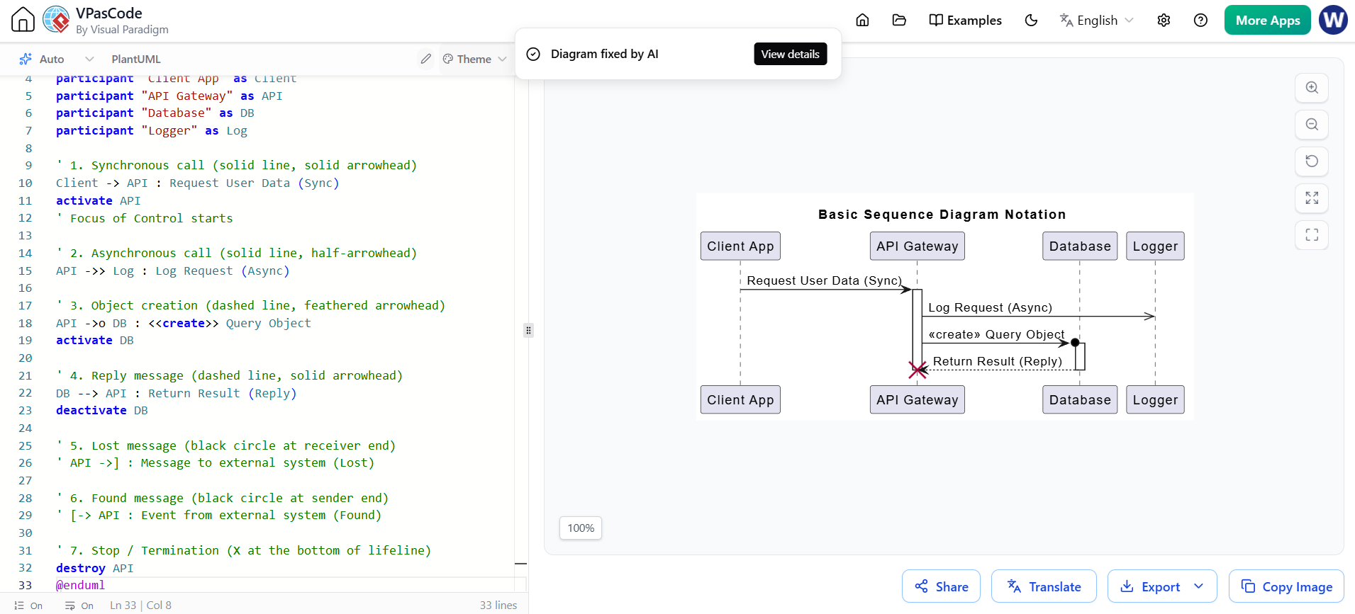
@startuml Basic_Sequence_Notation
title Basic Sequence Diagram Notation

participant "Client App" as Client
participant "API Gateway" as API
participant "Database" as DB
participant "Logger" as Log

' 1. Synchronous call (solid line, solid arrowhead)
Client -> API : Request User Data (Sync)
activate API
' Focus of Control starts

' 2. Asynchronous call (solid line, half-arrowhead)
API ->> Log : Log Request (Async)

' 3. Object creation (dashed line, feathered arrowhead)
API ->o DB : <<create>> Query Object
activate DB

' 4. Reply message (dashed line, solid arrowhead)
DB --> API : Return Result (Reply)
deactivate DB

' 5. Lost message (black circle at receiver end)
API ->] : Message to external system (Lost)

' 6. Found message (black circle at sender end)
[-> API : Event from external system (Found)

' 7. Stop / Termination (X at the bottom of lifeline)
destroy API
@enduml
Sequence diagrams are not just for drawing pretty pictures; they serve critical analytical and design purposes:
Real-world systems are rarely linear. UML 2.0 introduces advanced constructs to handle complex logic, branching, and concurrency within sequence diagrams.
Combined fragments allow you to model conditional logic, loops, and parallel processing using specific interaction operators:
alt (Alternative): Represents a choice of behaviors based on guards (similar to if/else statements). Only one operand is executed.loop (Loop): Repeats an operand a specified number of times or while a condition is true (similar to while or for loops).opt (Option): A specific choice where either the behavior happens or nothing happens (similar to an if statement without an else).par (Parallel): Represents a parallel merge of behaviors, indicating that multiple operands are executed concurrently.Instead of redrawing the same complex sequence of messages across multiple diagrams, Interaction Occurrences allow you to factor out and reference common behavior. You can define a complex interaction once and reference it as a single message in other diagrams, keeping your models clean and modular.
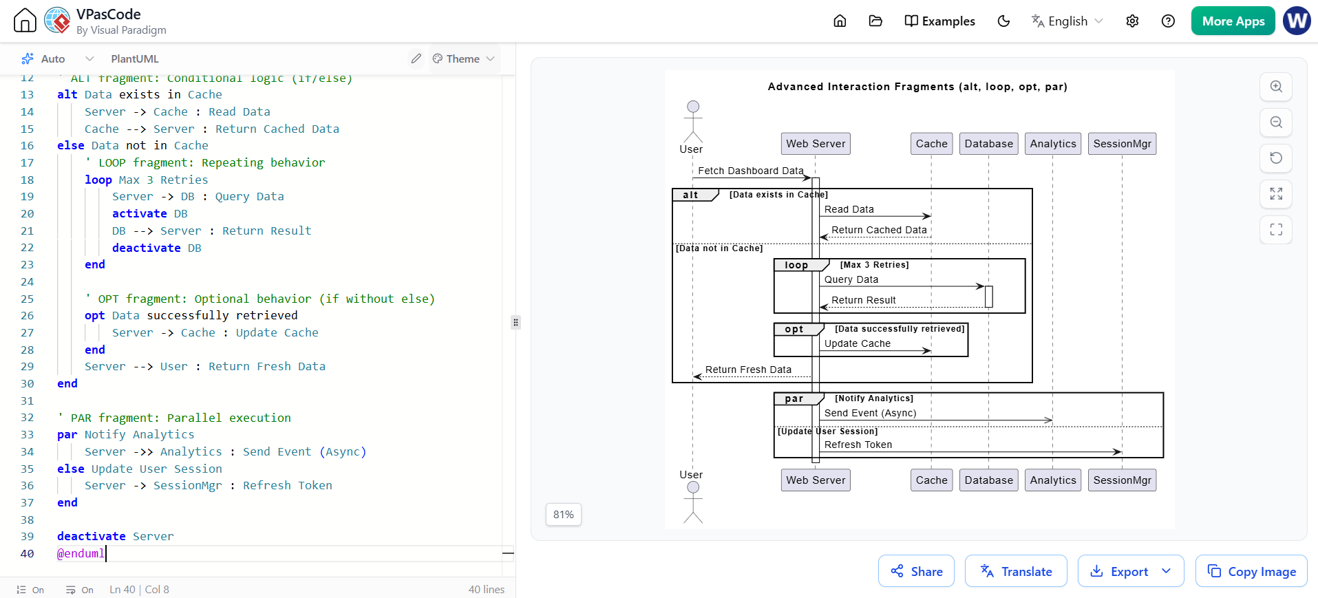
@startuml Advanced_Interaction_Fragments
title Advanced Interaction Fragments (alt, loop, opt, par)

actor User
participant "Web Server" as Server
participant "Cache" as Cache
participant "Database" as DB

User -> Server : Fetch Dashboard Data
activate Server

' ALT fragment: Conditional logic (if/else)
alt Data exists in Cache
    Server -> Cache : Read Data
    Cache --> Server : Return Cached Data
else Data not in Cache
    ' LOOP fragment: Repeating behavior
    loop Max 3 Retries
        Server -> DB : Query Data
        activate DB
        DB --> Server : Return Result
        deactivate DB
    end

    ' OPT fragment: Optional behavior (if without else)
    opt Data successfully retrieved
        Server -> Cache : Update Cache
    end
    Server --> User : Return Fresh Data
end

' PAR fragment: Parallel execution
par Notify Analytics
    Server ->> Analytics : Send Event (Async)
else Update User Session
    Server -> SessionMgr : Refresh Token
end

deactivate Server
@enduml
It is common to confuse sequence diagrams with communication diagrams (formerly known as collaboration diagrams in UML 1.x). It is important to note that the two are semantically equivalent—meaning they contain the exact same underlying information and can be converted into one another without losing data. However, they differ significantly in their visual emphasis:
| Feature | Sequence Diagrams | Communication Diagrams |
|---|---|---|
| Primary Emphasis | Temporal order of messages over time. | Architectural structure and relationships between objects. |
| Layout | Vertical axis represents time; horizontal axis represents different objects. | Objects are arranged spatially; links connect them. |
| Ordering Mechanism | Relies on the vertical placement of messages (top-to-bottom). Does not use sequence numbers. | Uses sequence numbers (e.g., 1.0, 1.1, 2.0) on the message labels to indicate order. |
| Key Visual Elements | Lifelines and Focuses of Control (activation bars). | Links between objects and nested sequence numbers. |
Rule of thumb: Use sequence diagrams when the timing and exact order of execution are the most critical factors. Use communication diagrams when you want to emphasize the structural relationships and the specific objects involved in a complex web of interactions.
UML 2.0 Sequence Diagrams are an indispensable tool in the software engineer's toolkit. By providing a clear, time-ordered visualization of object interactions, they bridge the gap between abstract functional requirements and concrete object-oriented design.
Mastering the basic notation—such as lifelines, message types, and focuses of control—allows you to map out simple workflows. Meanwhile, leveraging advanced features like combined fragments (alt, loop, opt, par) and interaction occurrences empowers you to model highly complex, concurrent, and conditional system behaviors. Whether you are documenting an existing system or designing a new one from scratch, sequence diagrams ensure that your team shares a unified, precise understanding of how the system behaves over time.

