
In the realm of software engineering and systems analysis, understanding what a system must do is just as critical as understanding how it will do it. Enter the Use Case Diagram, a foundational behavioral diagram in the Unified Modeling Language (UML) 2.0.
A use case diagram is a visual representation that shows a set of use cases, actors, and the relationships among them. It serves as the primary means to capture the functional requirements of a system, acting as a bridge between the stakeholders who need the system and the developers who will build it. This comprehensive guide will walk you through the key concepts, relationships, organizational best practices, and the crucial textual descriptions that bring use case diagrams to life.
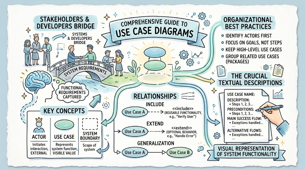
To effectively model a system, you must first understand its core building blocks. UML 2.0 defines three primary elements in a use case diagram:
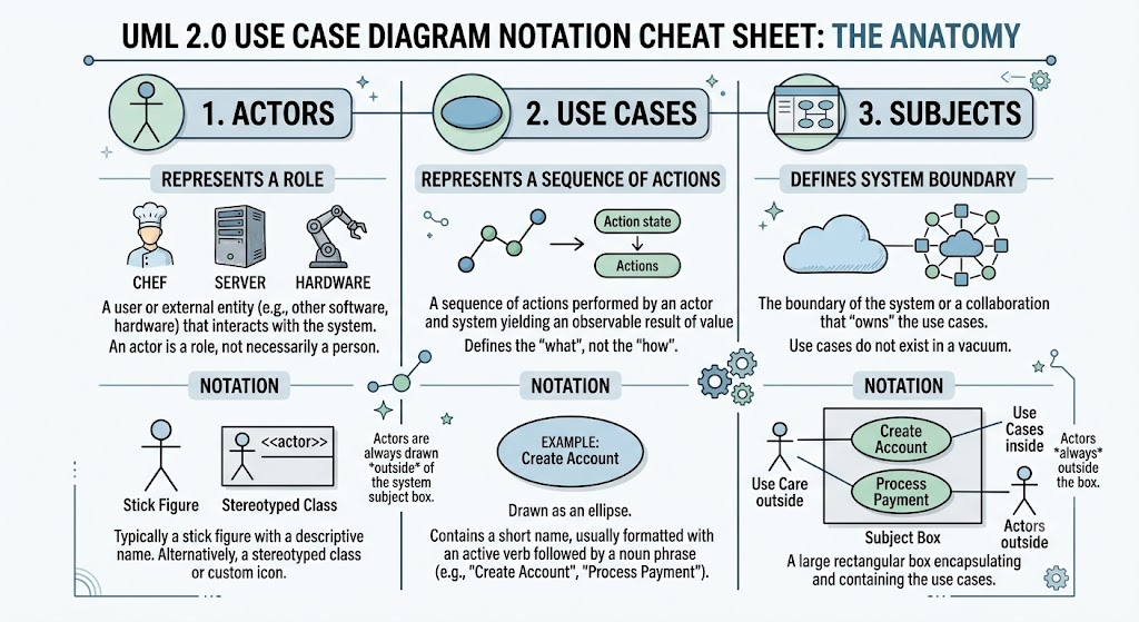
An actor represents a role that a user plays with regard to the system, or an external entity (such as another software system, a hardware device, or a database) that interacts with it. It is important to note that an actor is a role, not necessarily a specific person; a single person might play multiple actor roles.
Notation: Typically depicted as a simple stick figure with a descriptive name next to it. Alternatively, it can be represented as a stereotyped class or a custom user-defined icon.
Use cases represent a specific sequence of actions performed by an actor and the system that yields an observable result of value for that actor. They define the "what" without getting bogged down in the "how."
Notation: Drawn as an ellipse. Inside the ellipse is a short name, typically formatted with an active verb followed by a noun phrase (e.g., "Create Account", "Process Payment").
A use case does not exist in a vacuum; it is associated with a subject. The subject is the boundary of the system itself, or a specific collaboration within the system, which "owns" the use cases.
Notation: Represented by a large rectangular box that encapsulates and contains the use cases. Actors are always drawn outside of this subject box.
UML provides specific constructs to factor out common behavior, manage optional paths, and establish hierarchies within these diagrams.
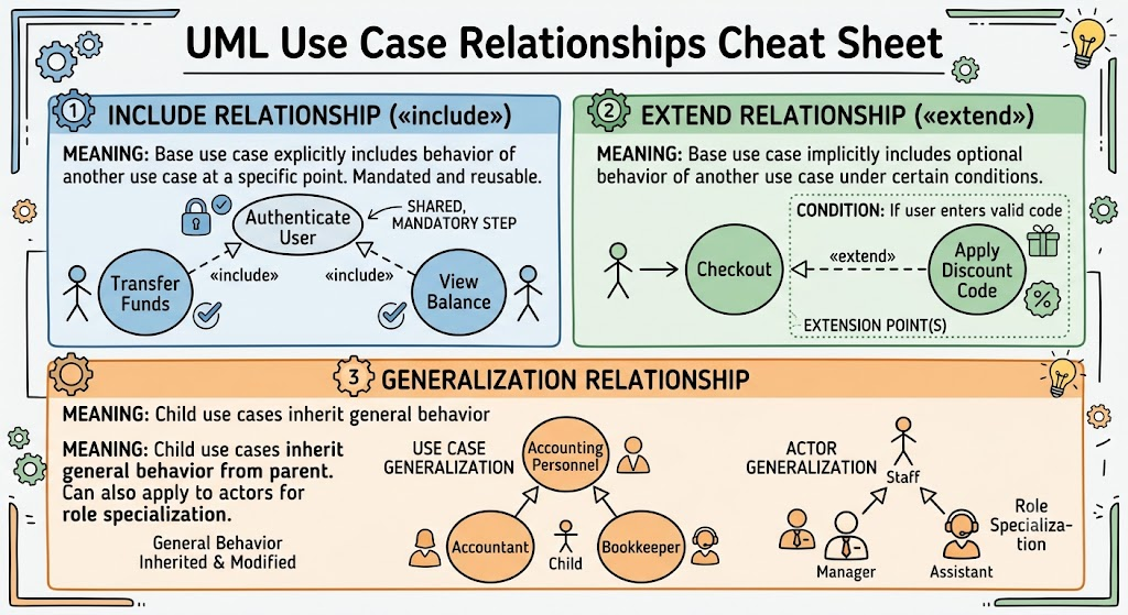
Include («include»): This relationship signifies that a base use case explicitly includes the behavior of another use case at a specific point in its execution. It is highly useful for reusing common, mandatory behavior across multiple use cases (e.g., "Authenticate User" included in both "Transfer Funds" and "View Balance").
Extend («extend»): This shows that a base use case implicitly includes the behavior of another use case at one or more defined extension points. This is typically used for optional behavior, error handling, or actions that occur only under certain specific conditions (e.g., "Apply Discount Code" extending "Checkout").
Generalization: Similar to class inheritance in object-oriented programming, a parent use case defines general behavior that "child" use cases can inherit, override, or add to. This concept can also be applied to actors to show role specialization (e.g., an "Accountant" actor specializing a more general "Accounting Personnel" actor).
Creating a use case diagram for a complex system can quickly result in a tangled "spaghetti" mess of lines and ellipses. To maintain clarity and utility, follow these practical organizational tips:
One Diagram per Actor: It is often highly beneficial to draw a separate, focused diagram for each primary actor. This prevents visual clutter and makes it easier for stakeholders to understand their specific interactions with the system.
Layering: Use different layers of diagrams to manage system complexity. Start with an "executive summary" layer that shows only the highest-level, most critical use cases. Subsequent layers can then delve into more specialized, detailed use cases.
Connection to Design: Use case text and diagrams should not exist in isolation. They should ideally make explicit connections to domain model classes and boundary classes (like specific HTML pages, UI windows, or API endpoints) to help system designers seamlessly translate requirements into technical designs.
While the diagram shows the structural relationships, the accompanying use case text describes the actual behavioral paths through the use case. A diagram without text is just a map; the text is the journey. Robust use case text should adhere to the following rules:
Use the Active Voice: Write from the actor’s perspective to clearly establish who is doing what.
Use the Present Tense: Keep the narrative immediate and active.
Follow a "Call and Response" Format: Clearly delineate interactions (e.g., "The Customer enters their credit card details; The system validates the card format").
Define the Courses of Action:
Clearly define a basic course of action (the "sunny-day scenario" where everything goes perfectly).
Provide exhaustive alternate courses to handle errors, exceptions, or infrequent paths.
End with Value: Every use case must conclude with a measurable result of value for the actor.
Below are examples of how these concepts translate into actual UML diagrams, written in PlantUML syntax.
This example demonstrates the basic layout of actors, use cases, and the subject boundary.
@startuml
left to right direction
skinparam packageStyle rectangle

actor "Customer" as cust
actor "System Admin" as admin

rectangle "E-Commerce System" as subject {
  usecase "Browse Products" as UC1
  usecase "Place Order" as UC2
  usecase "Manage Inventory" as UC3
}

' Associations between actors and use cases
cust --> UC1
cust --> UC2
admin --> UC3
@enduml
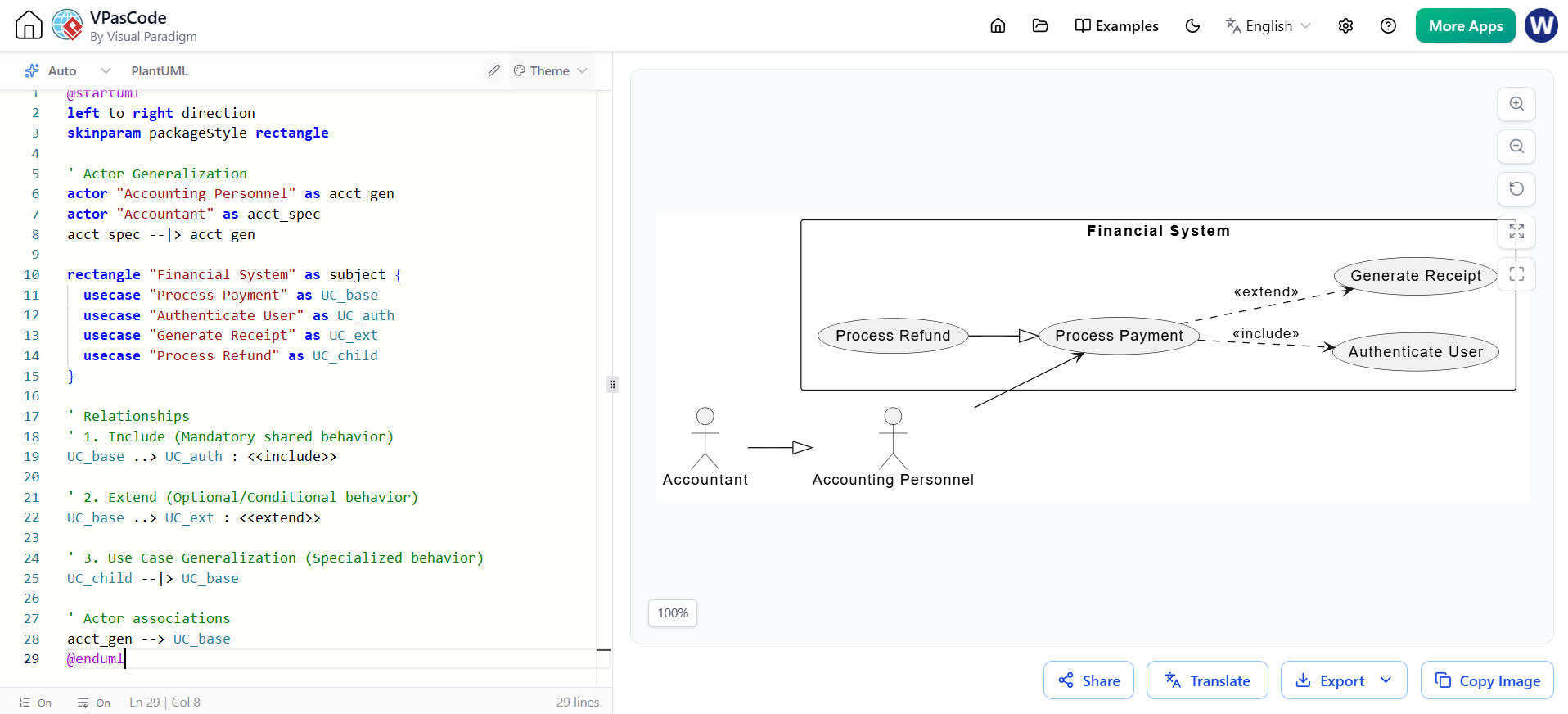
This example illustrates the complex relationships between use cases and actors.
@startuml
left to right direction
skinparam packageStyle rectangle

' Actor Generalization
actor "Accounting Personnel" as acct_gen
actor "Accountant" as acct_spec
acct_spec --|> acct_gen

rectangle "Financial System" as subject {
  usecase "Process Payment" as UC_base
  usecase "Authenticate User" as UC_auth
  usecase "Generate Receipt" as UC_ext
  usecase "Process Refund" as UC_child
}

' Relationships
' 1. Include (Mandatory shared behavior)
UC_base ..> UC_auth : <<include>>

' 2. Extend (Optional/Conditional behavior)
UC_base ..> UC_ext : <<extend>>

' 3. Use Case Generalization (Specialized behavior)
UC_child --|> UC_base

' Actor associations
acct_gen --> UC_base
@enduml
UML 2.0 Use Case Diagrams are an indispensable tool in the software development lifecycle. By visually mapping out the interactions between actors and use cases within a defined subject, teams can ensure that all functional requirements are captured and understood.
However, a diagram is only half the equation. By adhering to organizational best practices—such as layering and creating actor-specific diagrams—and by pairing the visual model with robust, active-voice use case text, teams can eliminate ambiguity. Ultimately, mastering both the visual and textual aspects of use cases ensures a smooth transition from high-level business requirements to concrete, value-driven system design.

