In the rapidly evolving landscape of software and systems engineering, clear communication between stakeholders, developers, and business analysts is paramount. Enter the Unified Modeling Language (UML), a standardized visual language that has become the industry benchmark for specifying, visualizing, constructing, and documenting complex systems. This article provides a comprehensive, self-contained overview of UML based on foundational principles, exploring its core concepts, relationship with object-oriented design, practical guidelines, and actionable tips for effective modeling.
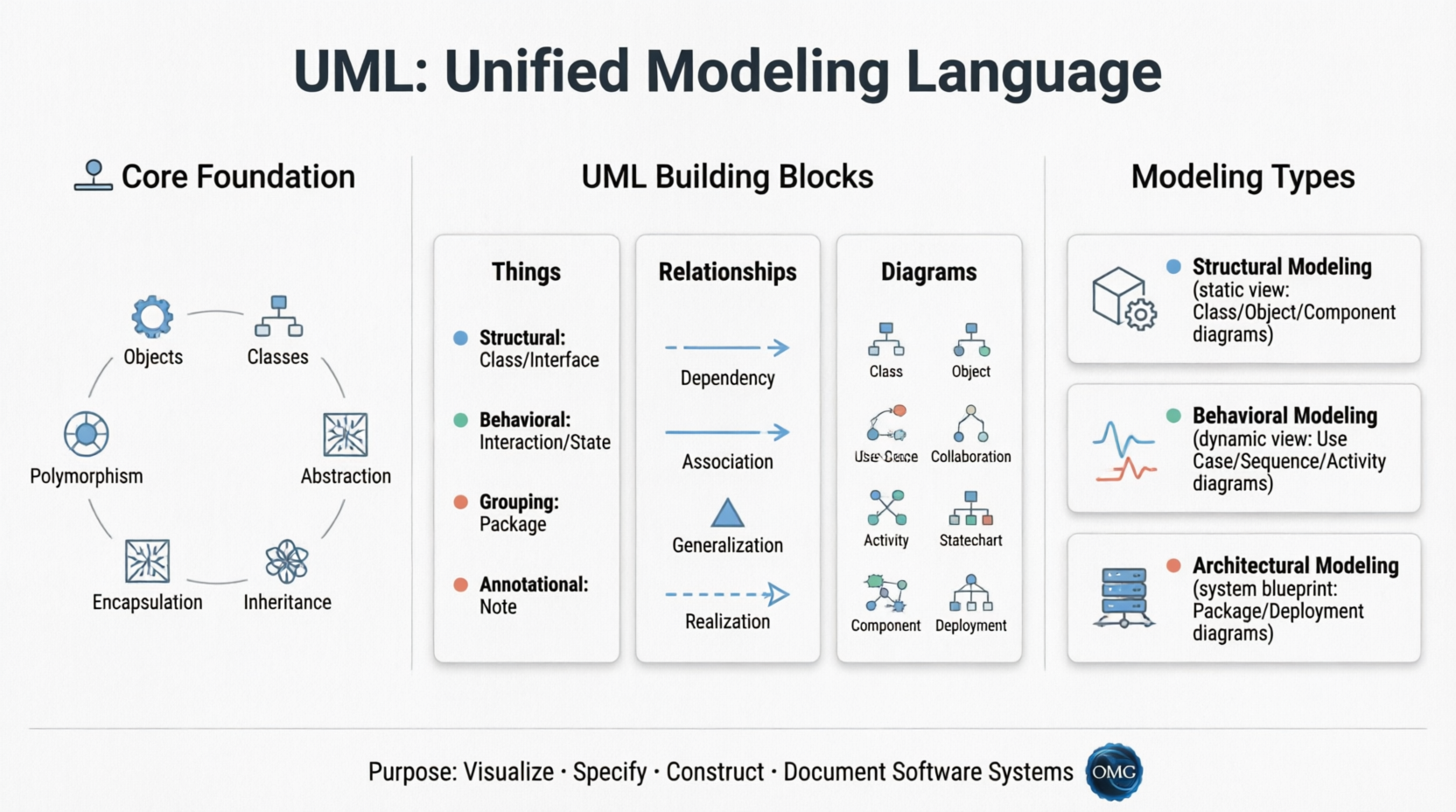
UML stands for Unified Modeling Language. It is a general-purpose, pictorial modeling language designed to create software blueprints. Unlike programming languages such as Java, C++, or Python, Javascript, UML is not used to write executable code directly. Instead, it serves as a visual representation of system architecture, behavior, and structure.
Key Characteristics:
The driving philosophy behind UML can be summarized by the adage: "A picture is worth a thousand words." Before UML, object-oriented development lacked a standardized methodology to organize and consolidate designs. UML was developed to solve this fragmentation.
Primary Goals:
Before drawing any UML diagram, practitioners must build a conceptual model. A conceptual model is a representation made of real-world concepts and their relationships. It acts as the cognitive foundation for accurate system modeling.
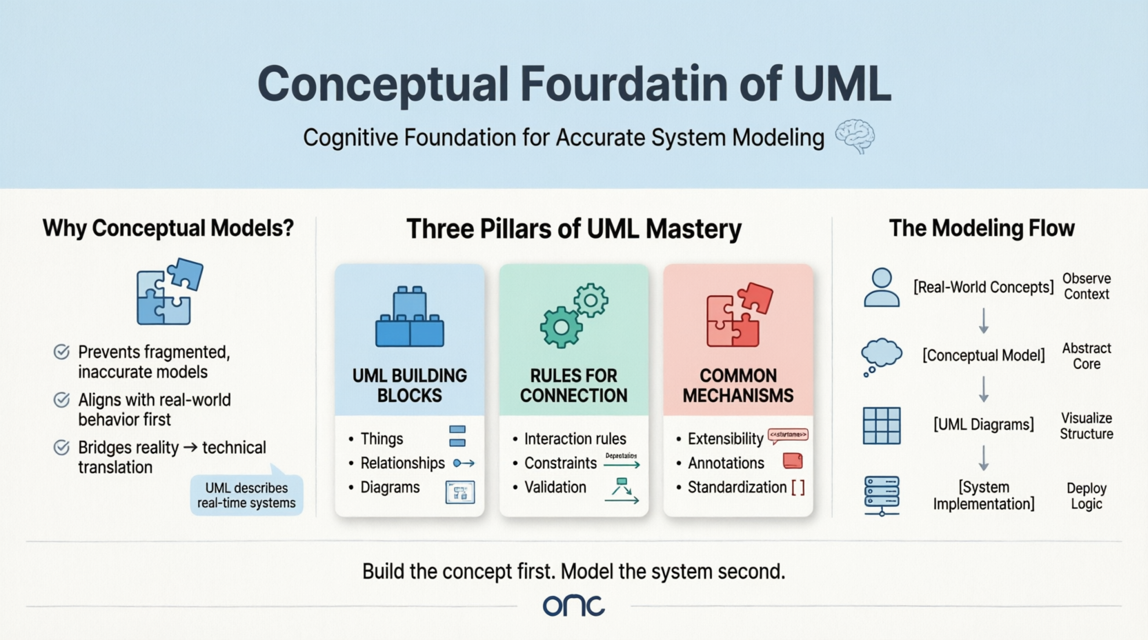
Why is it required?
UML describes real-time systems. Jumping straight into diagrams without understanding the underlying entities and their interactions leads to fragmented, inaccurate models. A conceptual model ensures alignment with real-world behavior before technical translation begins.
The Three Pillars of UML Mastery:
UML is the direct successor to Object-Oriented (OO) Analysis and Design. It inherits and visually represents the core tenets of the object-oriented paradigm:
| OO Concept | UML Representation | Purpose |
|---|---|---|
| Objects | Instances/Nodes | Real-world entities with state and behavior |
| Classes | Rectangular Diagrams | Blueprints defining shared properties and methods |
| Abstraction | Interfaces & Use Cases | Hiding complexity, exposing only essential behavior |
| Encapsulation | Class Boundaries | Binding data and methods, restricting external access |
| Inheritance | Generalization Arrows | Creating specialized classes from generalized ones |
| Polymorphism | Interface Realization | Allowing entities to exist and behave in multiple forms |
UML diagrams are essentially visual translations of these OO concepts. Without a solid grasp of object-oriented principles, effective UML modeling is nearly impossible.
UML does not exist in a vacuum; it is the visual output of a structured OO workflow. The pipeline consists of three sequential phases:
UML acts as the bridge between Phase 1/2 and Phase 3, transforming abstract OO concepts into standardized, shareable diagrams.
In modern engineering, UML diagrams are fundamentally object-centric. Whether modeling static structures (Class Diagram), dynamic behaviors (Sequence Diagram), or architectural deployments (Deployment Diagram), the underlying artifacts remain objects and their interactions.
How UML Integrates with OO Design:
The stronger the OO foundation, the more accurate and actionable the UML diagrams become.
To leverage UML effectively, follow these foundational guidelines:
✅ Start Conceptually: Always map real-world entities and relationships before opening a modeling tool.
✅ Align with Stakeholders: UML is for business users, testers, and developers alike. Adjust diagram complexity to your audience.
✅ Iterate Incrementally: Diagrams should be built, reviewed, and refined iteratively. Avoid attempting a "perfect" model on the first draft.
✅ Focus on Purpose: Every diagram must serve a clear objective (e.g., requirement gathering, architecture validation, or code generation).
✅ Keep It Minimal: Include only necessary attributes, methods, and relationships. Overcomplication defeats UML's purpose.
✅ Use Annotations: Leverage notes and comments to clarify constraints, assumptions, or business rules that aren't immediately visible in notation.
| Challenge | Tip/Trick |
|---|---|
| Diagrams become too cluttered | Break large systems into multiple focused diagrams (e.g., one for authentication, one for order processing). Use Package diagrams to group related elements. |
| Stakeholders don't understand technical notation | Start with Use Case or Activity diagrams for business audiences. Reserve Class/Component diagrams for technical teams. |
| Maintaining diagram-code sync | Use integrated CASE tools that support forward/reverse engineering to auto-generate code skeletons or update diagrams when code changes. |
| Choosing the right diagram | Ask: Am I modeling structure (Class/Component), behavior (Sequence/Statechart/Activity), or requirements (Use Case)? Match the diagram to the question. |
| Avoiding methodology lock-in | Remember UML accompanies processes; it doesn't replace Agile, Waterfall, or DevOps. Integrate UML artifacts into your existing workflow, not the other way around. |
To illustrate how UML concepts translate into practice, consider a simple Online Order Processing System:
Customer, Order, Payment, Inventory, Shipping. Define responsibilities → Customer places order, Payment validates transaction, Inventory checks stock.Customer associates with Order. Order depends on Payment and Inventory. Shipping generalizes into Standard and Express delivery.Place Order, Process Payment, Track Shipment) with actors (Customer, Admin).Order class with attributes (orderID, status, total) and methods (calculateTotal(), confirm()), linked to Payment and Inventory.Customer → PlaceOrder() → Order → ValidatePayment() → Payment → Confirm() → Shipping → Dispatch().Web Server, Database Server, Payment Gateway API).This pipeline demonstrates how UML transforms abstract OO concepts into actionable, multi-perspective blueprints.
UML is far more than a collection of diagrams; it is a universal visual language that bridges the gap between abstract business requirements and concrete technical implementation. By grounding UML practice in object-oriented principles, building strong conceptual models, and aligning diagrams with stakeholder needs, teams can design systems that are robust, maintainable, and clearly understood across disciplines.
Whether you're architecting a microservice ecosystem, documenting a legacy migration, or modeling a manufacturing workflow, UML provides the standardized vocabulary needed to turn complexity into clarity. Master its foundations, respect its iterative nature, and let it accompany your development process as the blueprint it was always meant to be.