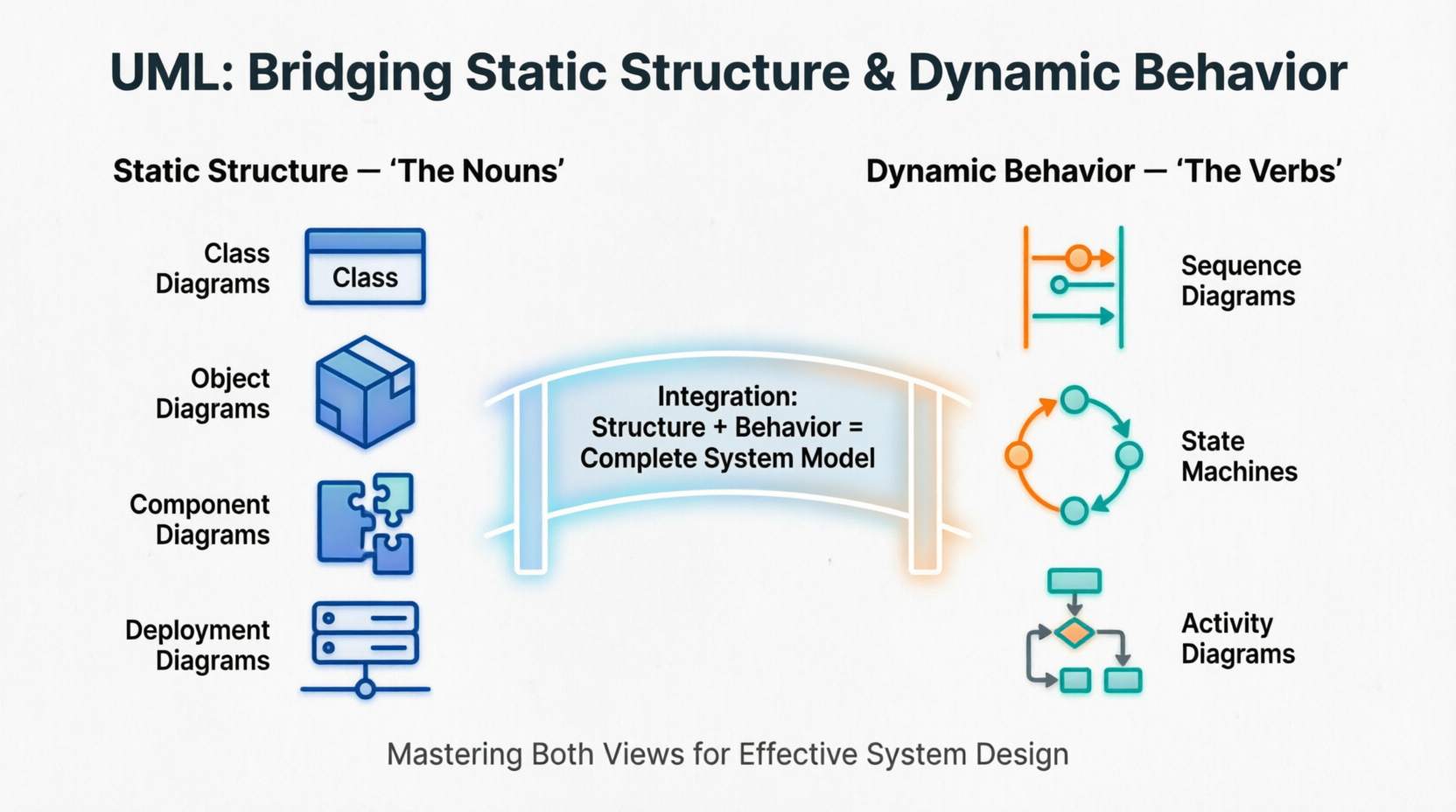
Unified Modeling Language (UML) stands as the industry standard for visualizing, specifying, constructing, and documenting software systems. At its core, UML provides a powerful framework that mirrors how we naturally understand complex systems: by distinguishing between what exists and what happens. This fundamental dichotomy—between the "nouns" of a system (its static structure) and the "verbs" (its dynamic behavior)—forms the backbone of effective system modeling.
Understanding this distinction is crucial for product managers, architects, and developers alike. Whether you're designing a cloud-based SaaS platform or optimizing an existing system, mastering both views enables you to create comprehensive models that capture not only the components of your system but also how they interact over time. This tutorial explores the dual nature of UML, providing practical insights into when and how to use structural versus behavioral diagrams, with real-world examples and tooling recommendations to streamline your modeling workflow.
Static structure defines the universe of discourse for a system. It answers the question: "What exists in my system?" Think of it as taking a snapshot of your system at a frozen moment in time, capturing all the elements and their relationships without considering how they change.
Structural things are the relatively stable parts of a model representing physical or conceptual elements. These include:
Classes: Blueprints for objects, defining attributes and operations
Interfaces: Contracts that specify behavior without implementation
Collaborations: Groups of roles and their interactions
Use Cases: Functional requirements from a user's perspective
Active Classes: Elements that own processes or threads
Components: Modular, replaceable parts of a system
Nodes: Physical hardware elements where components execute
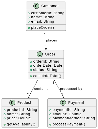
Class diagrams show the vocabulary of a system—the classes, interfaces, and their relationships. They define:
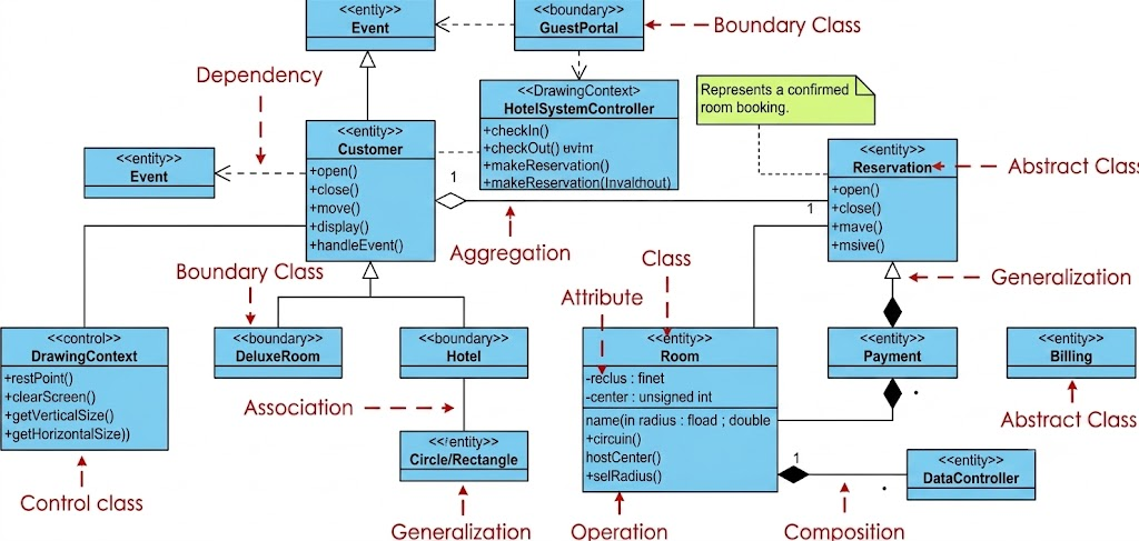
Attributes and methods of each class
Relationships (association, aggregation, composition, inheritance)
Multiplicity constraints
Visibility modifiers
Object diagrams represent static snapshots of instances found in class diagrams. They show:
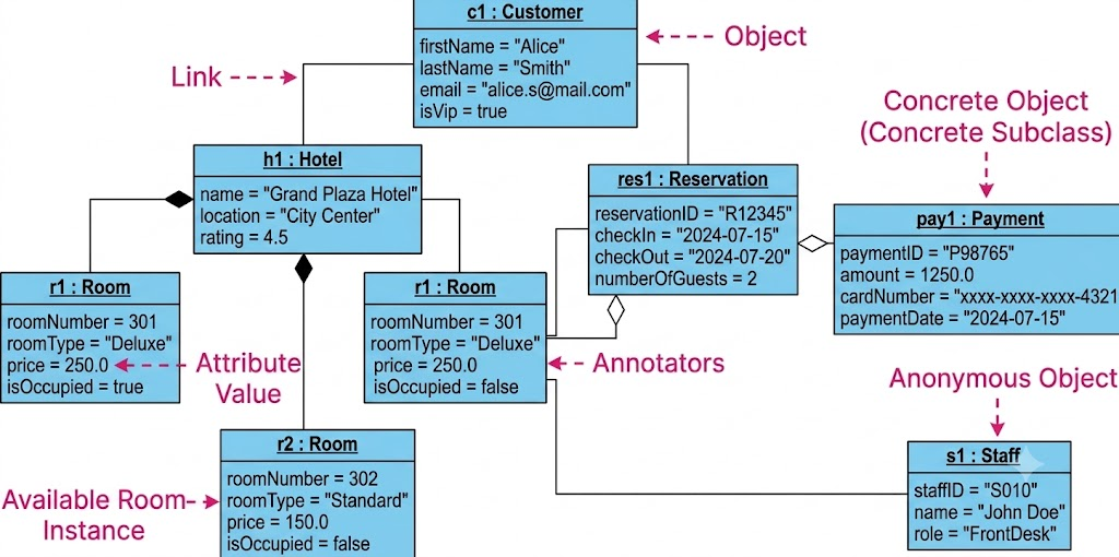
Specific object instances at a point in time
Actual values of attributes
Links between objects (instances of associations)
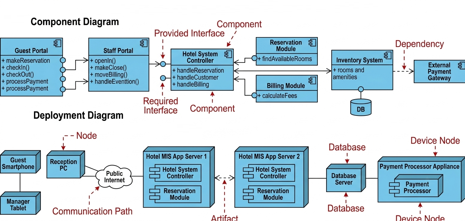
These address the physical implementation:
Component Diagrams: Show how software components are organized and depend on each other
Deployment Diagrams: Illustrate hardware topology and where components run
Structural semantics define the meaning of model elements as they exist at a single moment. This includes type constraints, relationship cardinalities, and visibility rules. The static view tells you what can exist but not how it changes.
Dynamic behavior describes how the system changes over time and how objects communicate to accomplish goals. It answers the question: "What happens in my system?" This view captures the flow of control, message passing, and state transitions that bring your static structure to life.
Behavioral things represent behavior over time and space. There are two primary types:
A set of messages exchanged among objects to accomplish a specific purpose. Interactions focus on:
Message sequences between objects
Collaboration patterns
Time-ordered communication
The sequences of states an object goes through during its lifetime in response to events. State machines capture:
Valid states an object can be in
Transitions triggered by events
Actions performed during transitions
These emphasize either time ordering or structural organization:
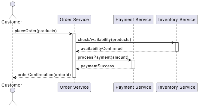
Sequence Diagrams: Show messages exchanged between objects in chronological order, emphasizing the time dimension
Communication (Collaboration) Diagrams: Focus on the structural organization of communicating objects, showing links and message flow
Focus on the event-ordered behavior of an object, especially useful for reactive systems. They show:
States and substates
Transitions with triggers, guards, and actions
Entry and exit behaviors
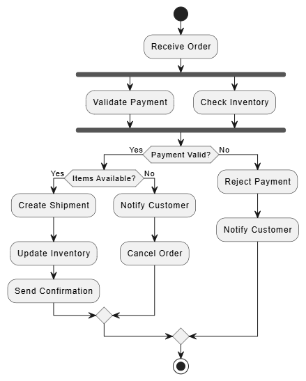
Emphasize the flow of control from activity to activity—essentially object-oriented flowcharts. They depict:
Sequential and parallel activities
Decision points and branches
Swimlanes for responsibility allocation
Behavioral semantics (or dynamic semantics) define the meaning of model elements that describe how individuals in the domain change over time. The dynamic view describes the history of objects and the valid sequences of snapshots that occur as the system moves from one state to another.
While UML distinguishes between static and dynamic views, they are deeply interconnected. Static structure is the foundation on which dynamic behavior is built; you cannot describe how something interacts without first defining what is interacting.
Behavioral elements connect to structural elements: A state machine describes the lifetime of a specific class; an interaction shows how instances of various classes collaborate.
Complementary perspectives: Class diagrams define the players; sequence diagrams show their dialogue. Component diagrams outline the architecture; deployment diagrams show where it runs.
Iterative refinement: Start with structural diagrams to establish the system's skeleton, then layer behavioral diagrams to animate it. Refine both views iteratively as requirements evolve.
Let's examine how static and dynamic views integrate in a real-world scenario:
Static View:
Classes: Customer, Order, Product, Payment, Inventory
Relationships: Customer places Order, Order contains Products, Payment processes Order
Dynamic View:
Sequence Diagram: Shows message flow from customer checkout → payment validation → inventory check → order confirmation
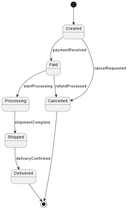
State Machine: Order transitions through states: Created → Paid → Shipped → Delivered
Activity Diagram: Depicts the workflow including parallel inventory checks and payment processing
PlantUML is an open-source tool that allows you to create UML diagrams from simple text descriptions. Below are examples demonstrating both static and dynamic views.
@startuml
class Customer {
  +customerId: String
  +name: String
  +email: String
  +placeOrder()
}

class Order {
  +orderId: String
  +orderDate: Date
  +status: String
  +calculateTotal()
}

class Product {
  +productId: String
  +name: String
  +price: Double
  +getAvailability()
}

class Payment {
  +paymentId: String
  +amount: Double
  +paymentMethod: String
  +processPayment()
}

Customer "1" --> "*" Order : places
Order "*" --> "*" Product : contains
Order "1" --> "1" Payment : processed by
@enduml
@startuml
actor Customer
participant "Order Service" as OrderSvc
participant "Payment Service" as PaySvc
participant "Inventory Service" as InvSvc

Customer -> OrderSvc: placeOrder(products)
activate OrderSvc
OrderSvc -> InvSvc: checkAvailability(products)
activate InvSvc
InvSvc --> OrderSvc: availabilityConfirmed
deactivate InvSvc
OrderSvc -> PaySvc: processPayment(amount)
activate PaySvc
PaySvc --> OrderSvc: paymentSuccess
deactivate PaySvc
OrderSvc --> Customer: orderConfirmation(orderId)
deactivate OrderSvc
@enduml
@startuml
state "Created" as Created
state "Paid" as Paid
state "Processing" as Processing
state "Shipped" as Shipped
state "Delivered" as Delivered
state "Cancelled" as Cancelled

[*] --> Created
Created --> Paid : paymentReceived
Paid --> Processing : startProcessing
Processing --> Shipped : shipmentComplete
Shipped --> Delivered : deliveryConfirmed
Created --> Cancelled : cancelRequested
Paid --> Cancelled : refundProcessed
Cancelled --> [*]
Delivered --> [*]
@enduml
@startuml
start
:Receive Order;
fork
  :Validate Payment;
fork again
  :Check Inventory;
end fork
if (Payment Valid?) then (Yes)
  if (Items Available?) then (Yes)
    :Create Shipment;
    :Update Inventory;
    :Send Confirmation;
  else (No)
    :Notify Customer;
    :Cancel Order;
  endif
else (No)
  :Reject Payment;
  :Notify Customer;
endif
stop
@enduml
While PlantUML excels at code-based diagram generation, Visual Paradigm offers a comprehensive, visual-first approach to UML modeling with enterprise-grade features.
Visual Paradigm is a leading UML modeling tool that supports the complete software development lifecycle. Its ecosystem provides:
All 14 UML 2.x diagram types
SysML for systems engineering
BPMN for business process modeling
ERD for database design
Wireframing and UI/UX design tools
Smart Class Diagram Editor: Drag-and-drop interface with automatic relationship detection
Code Engineering: Reverse engineer code to class diagrams and generate code from diagrams
Component & Deployment Modeling: Visual hardware topology mapping with drag-and-drop nodes
Interactive Sequence Diagrams: Create message flows with intuitive timeline editing
State Machine Simulator: Test and validate state transitions before implementation
Activity Diagram Execution: Simulate workflows to identify bottlenecks
IDE Plugins: IntelliJ IDEA, Eclipse, VS Code integration
Version Control: Git integration for collaborative modeling
Cloud Platform: Visual Paradigm Online for team collaboration and real-time editing
API Access: Automate diagram generation and integrate with CI/CD pipelines
Requirement Management: Link UML models to business requirements
Project Management: Gantt charts and resource allocation
Documentation Generation: Auto-generate HTML/PDF documentation from models
Team Collaboration: Role-based access, comments, and review workflows
Download: Choose between Desktop Edition (full features) or Online Edition (cloud-based collaboration)
Create Project: Select template based on your methodology (Agile, Waterfall, etc.)
Start with Structure: Build class diagrams to define your system's vocabulary
Add Behavior: Layer sequence diagrams and state machines to model interactions
Validate: Use built-in consistency checks to ensure structural and behavioral alignment
Generate Documentation: Export comprehensive model documentation for stakeholders
| Feature | PlantUML | Visual Paradigm |
|---|---|---|
| Learning Curve | Moderate (text-based syntax) | Low (visual drag-and-drop) |
| Collaboration | Version control dependent | Real-time cloud collaboration |
| Code Integration | Text files in repos | IDE plugins and code generation |
| Simulation | Limited | Full state machine and activity simulation |
| Enterprise Features | Minimal | Comprehensive (requirements, PM, docs) |
| Cost | Free (open source) | Freemium with enterprise licensing |
Recommendation: Use PlantUML for quick diagrams in documentation and version-controlled repositories. Use Visual Paradigm for comprehensive system modeling, team collaboration, and enterprise-scale projects requiring simulation and validation.
Start Simple: Begin with high-level class diagrams and key sequence diagrams before diving into detailed state machines.
Maintain Consistency: Ensure behavioral diagrams reference classes and relationships defined in structural diagrams.
Use the Right Diagram for the Right Purpose:
Class diagrams for system vocabulary
Sequence diagrams for complex interactions
State machines for objects with complex lifecycles
Activity diagrams for workflow and business processes
Iterate and Refine: Models should evolve with your understanding. Don't aim for perfection in the first pass.
Keep Diagrams Focused: Each diagram should tell a clear story. Avoid overcrowding with unnecessary details.
Validate Early: Use simulation features (available in tools like Visual Paradigm) to catch logical errors before implementation.
Document Assumptions: Include notes explaining design decisions, especially where behavioral choices impact structural design.
Mastering UML requires fluency in both its static and dynamic dimensions. The "nouns" of your system—the classes, components, and relationships—provide the essential foundation. The "verbs"—the interactions, state transitions, and workflows—bring that foundation to life, showing how your system behaves under real-world conditions.
By understanding when to use structural diagrams versus behavioral diagrams, and how they complement each other, you create models that are not just documentation artifacts but powerful communication and design tools. Whether you choose the code-based flexibility of PlantUML or the comprehensive visual environment of Visual Paradigm, the key is consistency: ensuring your dynamic behavior aligns with your static structure, and vice versa.
As systems grow in complexity, this dual perspective becomes increasingly valuable. Static diagrams help you manage architectural integrity, while behavioral diagrams help you validate logic and identify edge cases. Together, they form a complete picture that bridges the gap between abstract requirements and concrete implementation.
For product managers like yourself, this holistic understanding enables better collaboration with engineering teams, clearer requirement specification, and more effective roadmap planning. By mastering both views, you position yourself to drive product success through rigorous, visual thinking that translates seamlessly from concept to code.
Remember: great system design isn't just about knowing what exists—it's about understanding how everything works together over time. UML gives you the language to express both, empowering you to build systems that are not only well-structured but also behave exactly as intended.