
In the realm of software engineering and system design, establishing clear boundaries and contracts between different parts of a system is crucial for building maintainable and scalable applications. The Unified Modeling Language (UML) offers a robust set of tools to visualize these architectural decisions.
In UML Class and Component diagrams, Provided and Required interfaces model how classes or components publish what they can do versus what they need from others to function. This relationship is commonly illustrated using Lollipop (ball) and Socket (cup) notation, which visually fit together to show a complete dependency hookup. This guide provides a comprehensive breakdown of these concepts, how to model them visually, and when to apply them in your system designs.
To effectively model system interactions, it is essential to understand the foundational building blocks of interface modeling in UML.
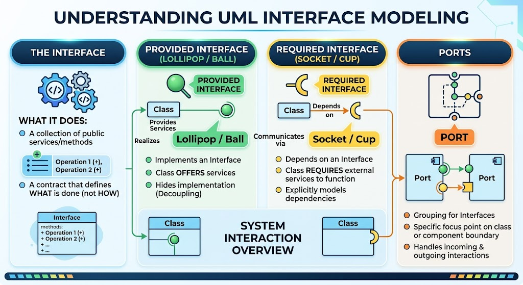
The Interface: An interface in UML is a collection of operations (methods or services) that represent the public services offered by a class or component. All operations within an interface inherently have public visibility. It acts as a strict contract: it defines what a service does, but deliberately hides how it is implemented.
Provided Interface (Lollipop / Ball): An interface that a class implements. It represents a service that the class offers to the outside world. When a class "realizes" an interface, it commits to providing the actual implementation for all operations defined within it. This promotes abstraction and decoupling, allowing other elements to interact with the class using a well-defined contract.
Required Interface (Socket / Cup): An interface that a class depends on. The class cannot do its job without some other object providing this interface. It explicitly models the external dependencies of a component, making it transparent what the component needs from the outside world to function properly.
Ports: In complex systems, Ports are used on the boundaries of classes or components to group these interfaces. A port serves as a specific focal point or "gateway," handling both incoming requests (via provided interfaces) and outgoing calls (via required interfaces).
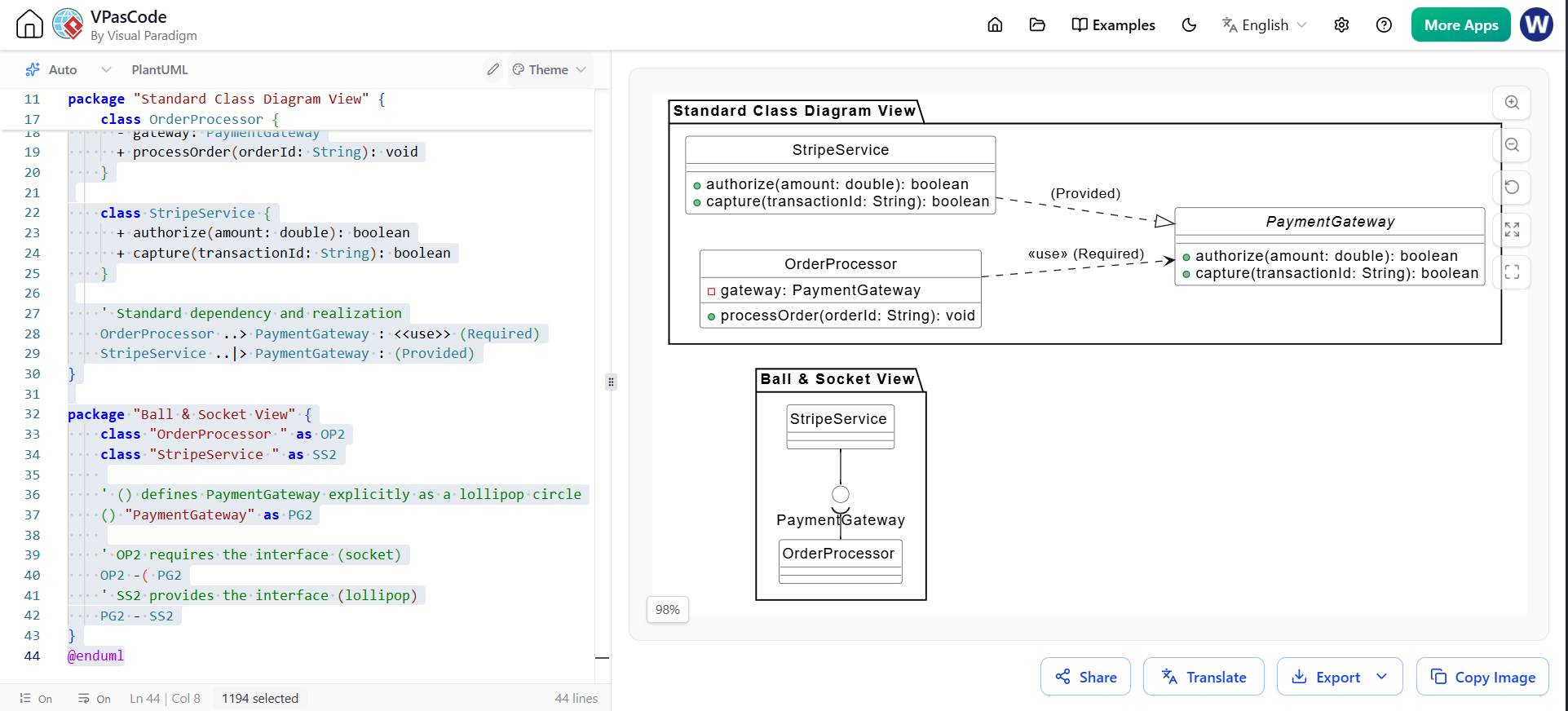
UML provides distinct, standardized visual symbols to differentiate between what a component gives and what it takes. When modeling these in modern diagramming suites, you have two primary ways to display these relationships:
| Notation Style | Visual Representation | Best Used For |
|---|---|---|
| Standard Class View | • Provided: A dashed line with a hollow triangle pointing to the interface block (Realization). • Required: A dashed arrow pointing from the class to the interface block (Dependency with a <<use>> stereotype). |
Detailed class design showing all methods, parameters, and return types within the interface block. |
| Ball & Socket View | • Provided: A solid line ending in a full circle (lollipop). • Required: A solid line ending in a semi-circle (socket) wrapping around the ball. |
High-level system architecture, component diagrams, and clarifying dependencies without cluttering the screen with method signatures. |
In a fully realized system model, provided and required interfaces are two sides of the same coin; they work together to form connections between components.
For example, in an e-commerce system, an Order class may have a required interface (a socket) called "Retrieve Books" because it needs that service to process a request. Conversely, an Inventory class would show "Retrieve Books" as a provided interface (a lollipop), signifying that it is the element capable of fulfilling that requirement. When the system is assembled, the required socket of the Order class connects to the provided lollipop of the Inventory class, completing the architectural circuit.
Let's look at a concrete design: an OrderProcessor class that needs to charge a customer's card. It shouldn't lock itself down to a specific payment provider (like Stripe or PayPal). Instead, it requires a generic interface, while a concrete class like StripeService provides that interface.
Here is how you represent this using text-based PlantUML markup (ideal for quick, automated rendering in tools like Visual Paradigm or VS Code):
@startuml
skinparam style strictuml
left to right direction

' Style tweaks for a clean, professional look
skinparam ClassBackgroundColor #FFFFFF
skinparam ClassBorderColor #333333
skinparam InterfaceBackgroundColor #FFFFFF
skinparam InterfaceBorderColor #333333

package "Standard Class Diagram View" {
    interface PaymentGateway {
      + authorize(amount: double): boolean
      + capture(transactionId: String): boolean
    }

    class OrderProcessor {
      - gateway: PaymentGateway
      + processOrder(orderId: String): void
    }

    class StripeService {
      + authorize(amount: double): boolean
      + capture(transactionId: String): boolean
    }

    ' Standard dependency and realization
    OrderProcessor ..> PaymentGateway : <<use>> (Required)
    StripeService ..|> PaymentGateway : (Provided)
}

package "Ball & Socket View" {
    class "OrderProcessor " as OP2
    class "StripeService " as SS2

    ' () defines PaymentGateway explicitly as a lollipop circle
    () "PaymentGateway" as PG2

    ' OP2 requires the interface (socket)
    OP2 -( PG2
    ' SS2 provides the interface (lollipop)
    PG2 - SS2
}
@enduml
(Note: The PlantUML syntax in the second section has been slightly adjusted to use standard valid markup for sockets --( and realization --|> to ensure it renders correctly in your diagramming tool, and the closing tag typo was fixed.)
Designing with provided and required interfaces is the foundation of loose coupling and the Dependency Inversion Principle (DIP). While standard class diagrams with simple dependency arrows are sufficient for basic object-oriented design, this pattern shines in specific scenarios:
Independent Testing: You can mock the required interface (PaymentGateway) easily to test your OrderProcessor logic without making real API calls.
Swappable Implementations: If you decide to switch from Stripe to PayPal, you only need to write a new class (PayPalService) that implements PaymentGateway. The OrderProcessor code remains completely untouched.
Component-Based Architecture: When designing systems composed of distinct, replaceable, and independently deployable components (like microservices or plugins).
Explicit Dependency Management: When you need to clearly communicate to other developers exactly what external services a module relies on to function, preventing "hidden dependencies."
Complex Boundary Modeling: When a single component has multiple distinct interaction points with the outside world, combining Ports with provided/required interfaces clarifies the exact entry and exit points.
Understanding and correctly applying Provided and Required interfaces in UML is a hallmark of mature software design. By shifting the focus from mere class structures to the services they offer and consume, architects and developers can create models that accurately reflect real-world system interactions.
Using the "lollipop" and "socket" notations not only makes component diagrams visually intuitive but also enforces a mindset of strict contractual boundaries and explicit dependencies. Whether you are designing a simple application module or a complex, distributed microservices architecture, mastering these interface concepts will lead to systems that are more decoupled, understandable, and ultimately, easier to maintain.

