
In the realm of software engineering and systems architecture, visualizing the dynamic behavior of a system is just as critical as defining its static structure. The UML Sequence Diagram is a premier interaction diagram designed specifically for this purpose. It emphasizes the chronological sequence in which messages are exchanged between participants, making it an indispensable tool for modeling use cases, designing APIs, and understanding complex system workflows.
Whether you are preparing for the Fundamental or Intermediate UML certification levels, mastering sequence diagrams is a central requirement. This comprehensive guide will walk you through the basic notation, the underlying semantics of event sequences, and advanced decomposition techniques, complete with practical PlantUML examples to solidify your understanding.
The foundation of any sequence diagram lies in its core visual elements. Understanding these building blocks is the first step toward UML Fundamental certification.
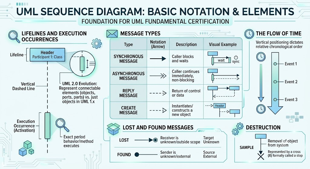
In a sequence diagram, time runs strictly from top to bottom. The vertical positioning of message arrows is not arbitrary; it dictates the relative chronological order of events.
Messages are the arrows connecting lifelines, representing the communication between participants. UML distinguishes several critical types:
->). The caller sends the message and waits (blocks) until the receiver's behavior terminates before continuing.->>). The caller sends the message and continues its execution immediately without waiting for a response.-->). It represents the return of control or data back to the caller.The removal of an object from the system is represented by a cross (X) at the bottom of its lifeline, formally referred to as a stop.
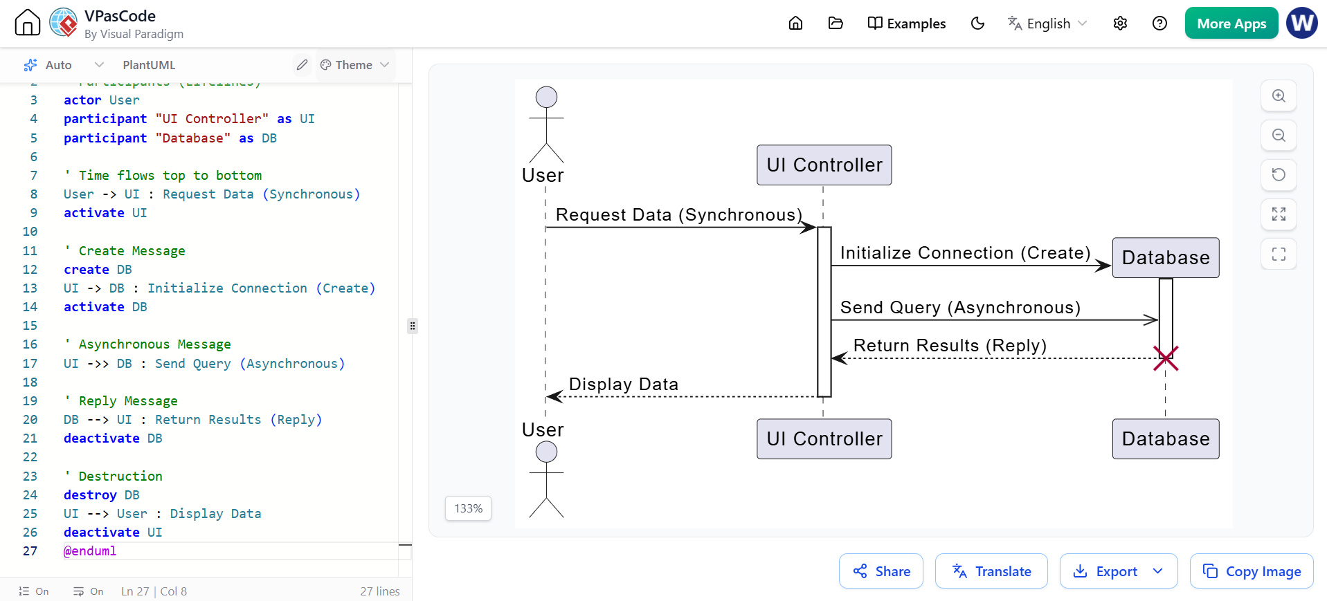
@startuml Basic_Notation
' Participants (Lifelines)
actor User
participant "UI Controller" as UI
participant "Database" as DB

' Time flows top to bottom
User -> UI : Request Data (Synchronous)
activate UI

' Create Message
create DB
UI -> DB : Initialize Connection (Create)
activate DB

' Asynchronous Message
UI ->> DB : Send Query (Asynchronous)

' Reply Message
DB --> UI : Return Results (Reply)
deactivate DB

' Destruction
destroy DB
UI --> User : Display Data
deactivate UI
@enduml
A sequence diagram is not just a drawing; it has strict mathematical semantics defined by the sets of valid and invalid event sequences (known as traces).
As systems grow in complexity, a single sequence diagram can become massive and unreadable. UML 2.0 introduces advanced decomposition mechanisms to manage this complexity, a key focus of the Intermediate UML certification.
Instead of redrawing complex, reusable logic, you can use an Interaction Reference. This is a frame containing the ref operator that points to another separate interaction diagram, keeping your current diagram clean and modular.
This technique allows modelers to "zoom into" a single lifeline. Instead of showing the lifeline as a black box, you can expand it to reveal the internal interactions of its sub-components.
Combined fragments use a rectangular frame with an interaction operator in the top-left corner to define complex control logic (loops, conditionals, parallel processing).
alt / opt:
alt defines conditional branches (if/else). It contains multiple operands separated by a dashed line; only one will execute based on the guard condition.opt defines optional behavior (if). It executes only if the condition is met.loop: Defines iterative sequences. The fragment repeats as long as the guard condition in the top-left of the operand is true.par: Defines parallel flows. Events inside the different operands of a par fragment can occur in any interleaved order, representing concurrent execution.break: Acts as an exception handler. If its condition is met, it terminates the enclosing interaction immediately.neg: Explicitly defines an invalid sequence of events. It is used to document behaviors that must never happen.Gates are specific connection points on the boundary of a combined fragment (like a ref frame). They link messages coming from outside the fragment to messages inside it, ensuring that the internal logic correctly interfaces with the external context.
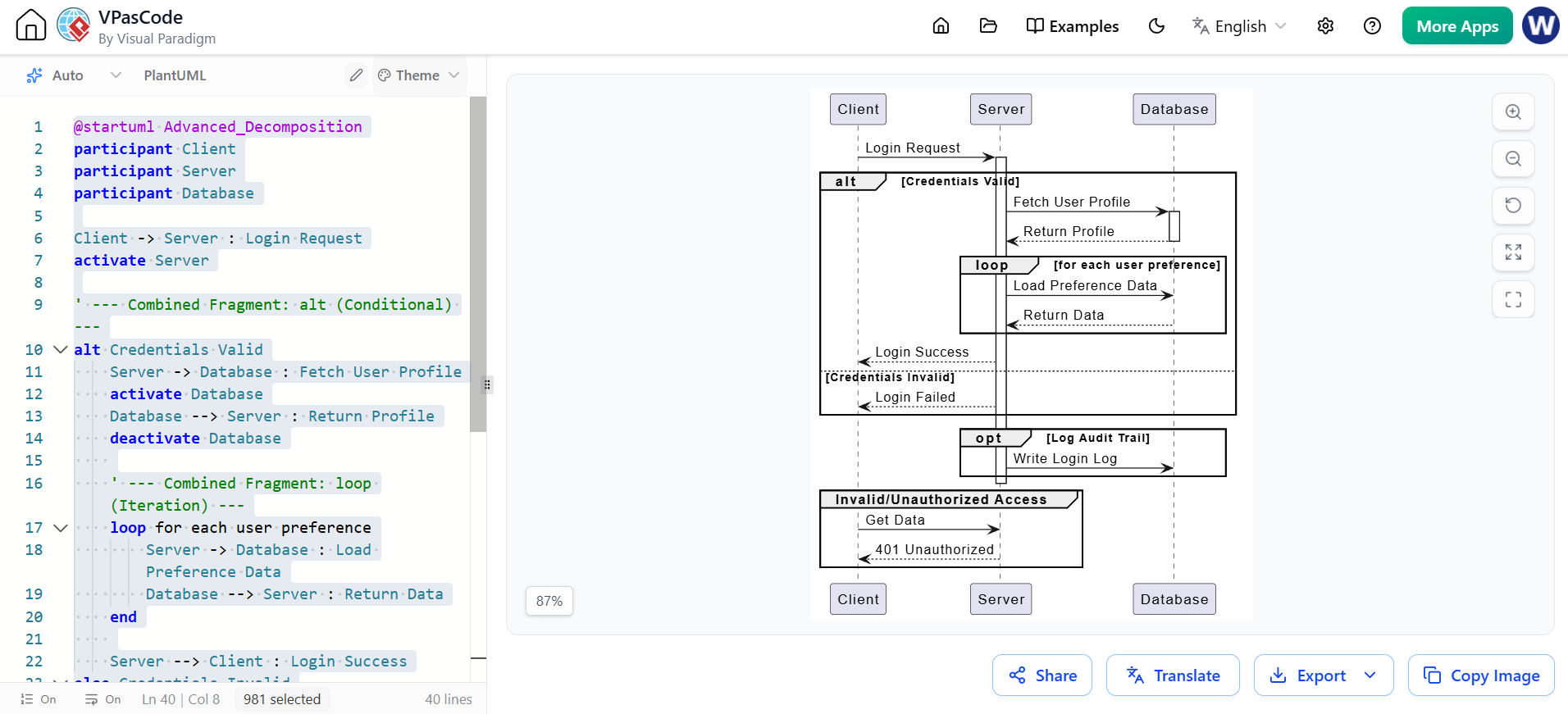
@startuml Advanced_Decomposition
participant Client
participant Server
participant Database

Client -> Server : Login Request
activate Server

' --- Combined Fragment: alt (Conditional) ---
alt Credentials Valid
    Server -> Database : Fetch User Profile
    activate Database
    Database --> Server : Return Profile
    deactivate Database

    ' --- Combined Fragment: loop (Iteration) ---
    loop for each user preference
        Server -> Database : Load Preference Data
        Database --> Server : Return Data
    end

    Server --> Client : Login Success
else Credentials Invalid
    Server --> Client : Login Failed
end

' --- Combined Fragment: opt (Optional) ---
opt Log Audit Trail
    Server -> Database : Write Login Log
end

deactivate Server

' --- Combined Fragment: neg (Invalid Sequence) ---
group Invalid/Unauthorized Access
    Client -> Server : Get Data
    Server --> Client : 401 Unauthorized
end

@enduml
To tie all concepts together, here is a comprehensive example of an E-Commerce checkout process. This diagram utilizes synchronous/asynchronous messages, object creation, destruction, and multiple combined fragments (alt, par, loop).
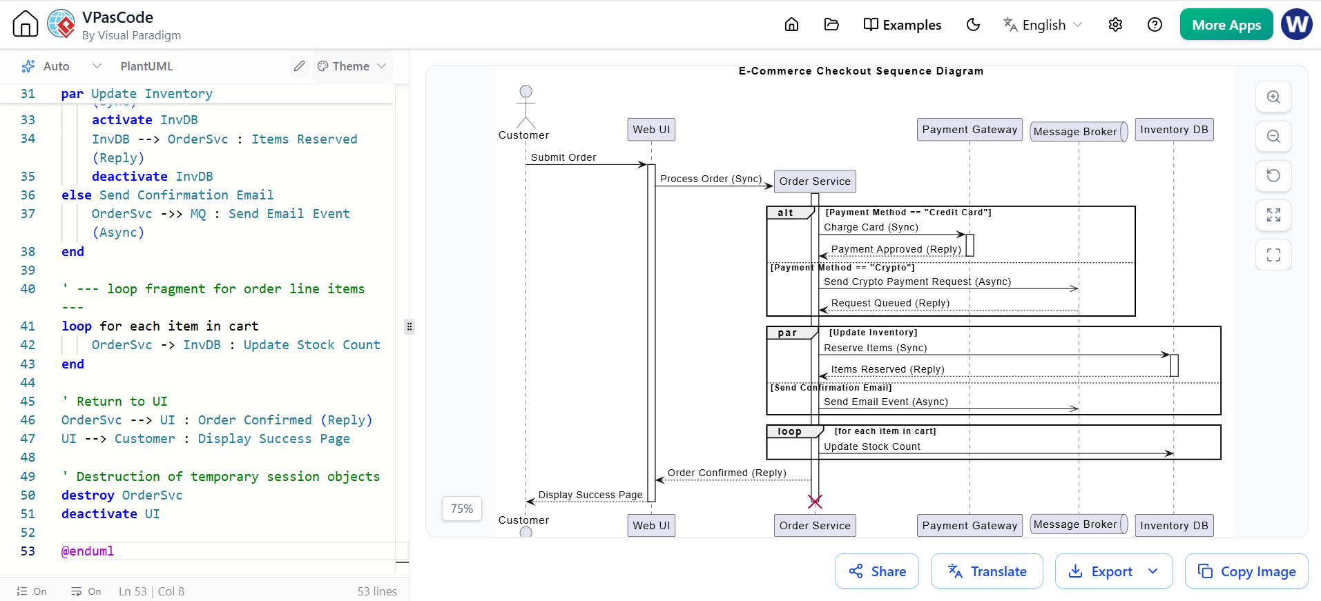
@startuml ECommerce_Checkout
title E-Commerce Checkout Sequence Diagram

actor Customer
participant "Web UI" as UI
participant "Order Service" as OrderSvc
participant "Payment Gateway" as PayGW
queue "Message Broker" as MQ
participant "Inventory DB" as InvDB

Customer -> UI : Submit Order
activate UI

' Create Message
create OrderSvc
UI -> OrderSvc : Process Order (Sync)
activate OrderSvc

' --- alt fragment for Payment Processing ---
alt Payment Method == "Credit Card"
    OrderSvc -> PayGW : Charge Card (Sync)
    activate PayGW
    PayGW --> OrderSvc : Payment Approved (Reply)
    deactivate PayGW
else Payment Method == "Crypto"
    OrderSvc ->> MQ : Send Crypto Payment Request (Async)
    MQ --> OrderSvc : Request Queued (Reply)
end

' --- par fragment for concurrent post-payment tasks ---
par Update Inventory
    OrderSvc -> InvDB : Reserve Items (Sync)
    activate InvDB
    InvDB --> OrderSvc : Items Reserved (Reply)
    deactivate InvDB
else Send Confirmation Email
    OrderSvc ->> MQ : Send Email Event (Async)
end

' --- loop fragment for order line items ---
loop for each item in cart
    OrderSvc -> InvDB : Update Stock Count
end

' Return to UI
OrderSvc --> UI : Order Confirmed (Reply)
UI --> Customer : Display Success Page

' Destruction of temporary session objects
destroy OrderSvc
deactivate UI

@enduml
UML Sequence Diagrams are a powerful, expressive tool for capturing the dynamic, time-ordered interactions within a system. By mastering the basic notation—such as lifelines, execution occurrences, and the various message types—you lay the groundwork for the Fundamental UML certification. Progressing to Intermediate concepts, such as combined fragments (alt, par, loop), interaction references, and semantic event sequencing, empowers you to model highly complex, enterprise-grade architectures with clarity and precision.
To bring these concepts to life in your own projects, robust and intuitive tooling is essential. Visual Paradigm is highly recommended for UML modeling. It offers a comprehensive suite of features that seamlessly supports everything from basic sequence diagrams to advanced UML 2.0 decomposition, complete with code generation, reverse engineering, and collaborative capabilities. By leveraging Visual Paradigm, you can ensure your sequence diagrams are not only semantically correct but also visually polished and perfectly aligned with industry standards.

