
In the realm of software engineering and systems analysis, Use Case Diagrams serve as the foundational blueprint for capturing the functional requirements of a system. At the very heart of every use case diagram lies the Actor.
An actor is defined as any entity that resides outside the system boundary but interacts with the system to achieve a specific goal. Identifying actors correctly is the critical first step in use case modeling; if you misidentify your actors, you will inevitably misidentify your use cases, leading to flawed system requirements.
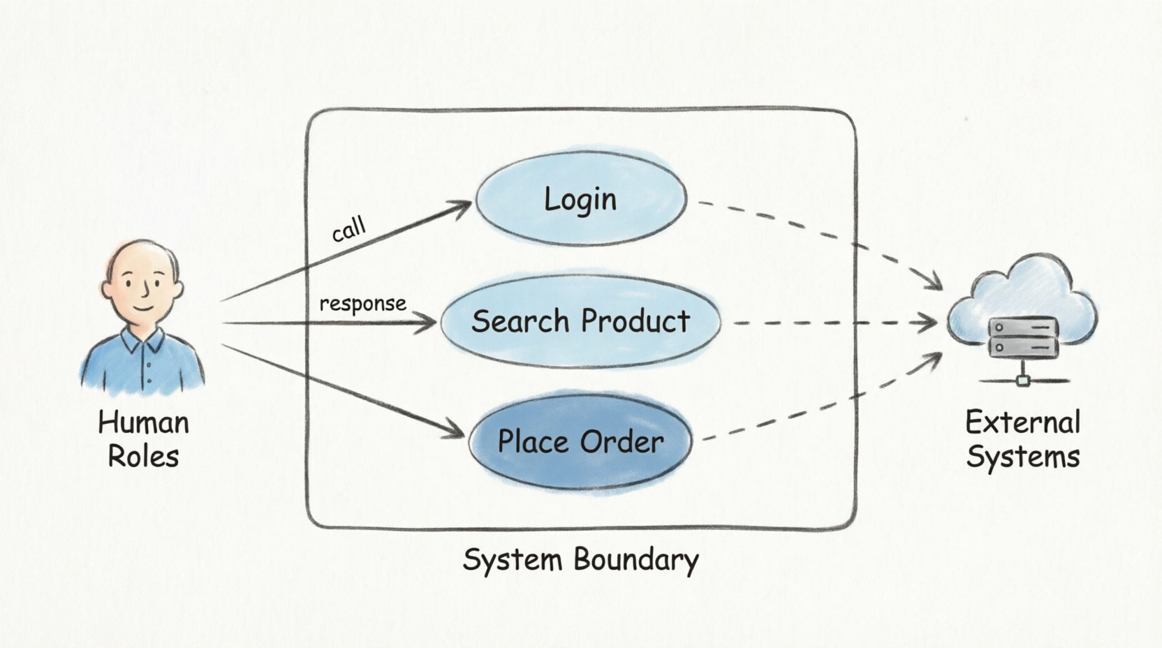
This guide provides a comprehensive framework for identifying, refining, and modeling actors in UML, ensuring that your system's functional boundaries are accurately and completely defined.
To accurately capture the functional requirements of a system, potential actors must be identified by looking outward from the system boundary. Actors generally fall into two primary categories: Human Roles and External Systems/Entities.
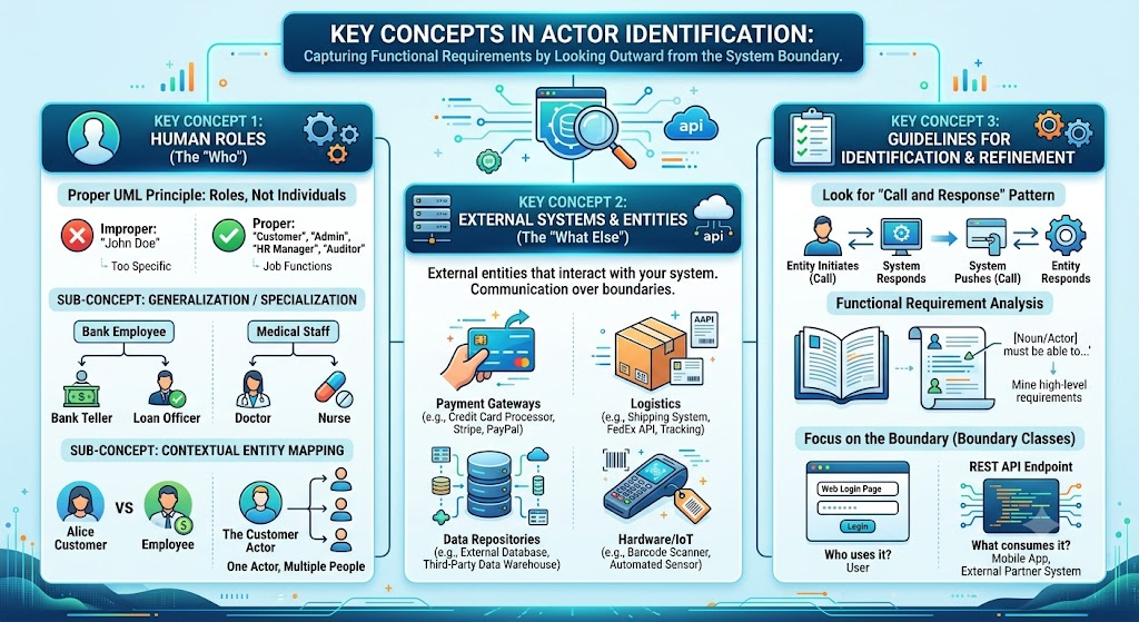
When identifying human actors, it is a fundamental UML principle that an actor must represent a role or a job function, rather than a specific individual person.
Examples of Proper vs. Improper Actor Naming:
Improper: "John Doe" (Too specific; John might leave the company).
Proper: "Customer", "System Administrator", "HR Manager", "Auditor".
Sub-Concept: Generalization and Specialization
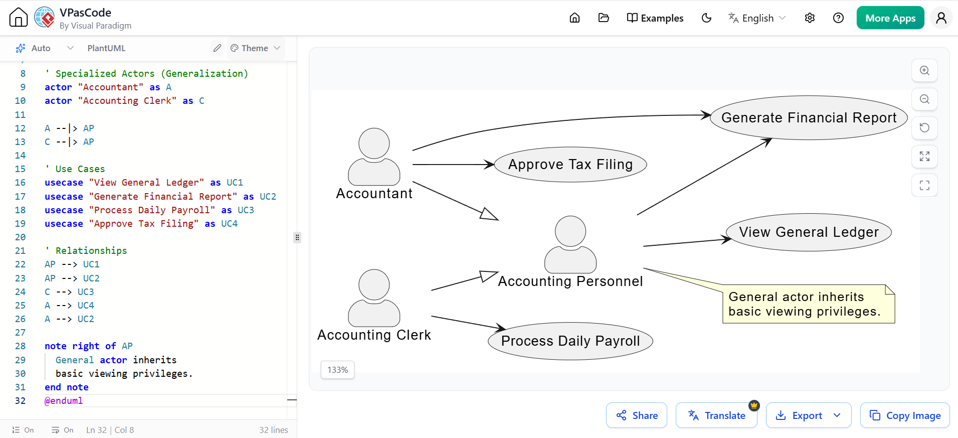
Actors can inherit traits from more general actors. This is useful when multiple roles share common use cases but also have specialized privileges.
Example 1 (Banking): A general actor named Bank Employee can perform basic tasks like "View Account Details". Specialized sub-actors include Bank Teller (can "Process Deposits") and Loan Officer (can "Approve Mortgages").
Example 2 (Healthcare): A general actor Medical Staff can "View Patient Records". Specialized sub-actors include Doctor (can "Prescribe Medication") and Nurse (can "Administer Medication").
Sub-Concept: Contextual Entity Mapping
It is crucial to understand the many-to-many relationship between physical people and UML actors.
One Person, Multiple Actors: "Alice" might be a Customer when she logs into the e-commerce portal to buy shoes, but she is an Employee when she logs into the internal HR portal to check her payroll.
One Actor, Multiple People: The Customer actor represents thousands of different physical individuals who all interact with the system in the exact same way.
Not all actors are human. In modern, interconnected architectures, systems must communicate with other systems. Any external entity that sends data to or receives data from your system is a potential actor.
Examples of External System Actors:
Payment Gateways: A Credit Card Processor (e.g., Stripe, PayPal) that validates transactions.
Logistics: A Shipping System (e.g., FedEx API) that calculates freight costs and generates tracking labels.
Data Repositories: An External Legacy Database or a Third-Party Data Warehouse that your system queries for historical data.
Hardware/IoT: An External Barcode Scanner or Automated Sensor that feeds data into the system.
Finding actors isn't always intuitive. Use the following guidelines to refine your actor list:
Look for the "Call and Response" Pattern:
To verify if an entity is truly an actor, check the interaction flow. Does the entity initiate an action (Call) to which the system responds? Or does the system push a notification/event (Call) to which the entity responds? If there is no direct interaction across the system boundary, it is not an actor.
Functional Requirement Analysis:
Mine your high-level requirements, user stories, and marketing materials. Look for nouns in phrases like: "The system shall allow the [Actor] to..." or "The [Actor] must be able to...".
Focus on the Boundary (Boundary Classes):
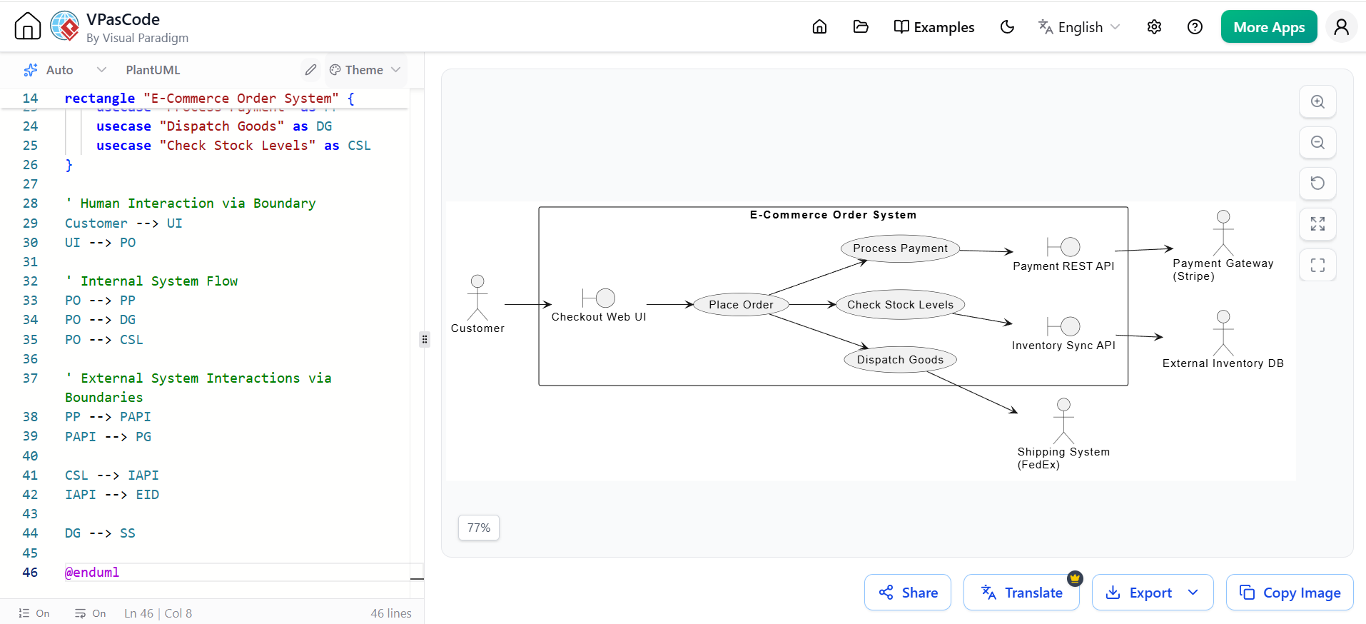
Trace the system's interfaces. If your system has a Web Login Page (a boundary class), ask yourself: Who uses this page? (Answer: The User). If your system exposes a REST API Endpoint (a boundary class), ask: What consumes this API? (Answer: The Mobile Application or External Partner System).
Below are PlantUML examples demonstrating how to model these concepts visually.
This diagram illustrates a financial system where general accounting roles are specialized into specific clerks and accountants, each with distinct use cases.
@startuml
left to right direction
skinparam actorStyle awesome

' General Actor
actor "Accounting Personnel" as AP

' Specialized Actors (Generalization)
actor "Accountant" as A
actor "Accounting Clerk" as C

A --|> AP
C --|> AP

' Use Cases
usecase "View General Ledger" as UC1
usecase "Generate Financial Report" as UC2
usecase "Process Daily Payroll" as UC3
usecase "Approve Tax Filing" as UC4

' Relationships
AP --> UC1
AP --> UC2
C --> UC3
A --> UC4
A --> UC2

note right of AP
  General actor inherits
  basic viewing privileges.
end note
@enduml
This diagram models an E-Commerce system. It highlights how external systems act as actors and how boundary classes (UI and API) are used to trace the interactions.
@startuml
left to right direction
skinparam packageStyle rectangle

' Human Actor
actor Customer

' External System Actors
actor "Payment Gateway\n(Stripe)" as PG
actor "Shipping System\n(FedEx)" as SS
actor "External Inventory DB" as EID

' System Boundary
rectangle "E-Commerce Order System" {

    ' Boundary Classes
    boundary "Checkout Web UI" as UI
    boundary "Payment REST API" as PAPI
    boundary "Inventory Sync API" as IAPI

    ' Use Cases
    usecase "Place Order" as PO
    usecase "Process Payment" as PP
    usecase "Dispatch Goods" as DG
    usecase "Check Stock Levels" as CSL
}

' Human Interaction via Boundary
Customer --> UI
UI --> PO

' Internal System Flow
PO --> PP
PO --> DG
PO --> CSL

' External System Interactions via Boundaries
PP --> PAPI
PAPI --> PG

CSL --> IAPI
IAPI --> EID

DG --> SS

@enduml
Identifying actors is the cornerstone of effective Use Case modeling. By strictly defining actors as roles rather than individuals, and by expanding your scope to include external systems and databases, you ensure that your system's functional boundaries are comprehensively mapped. Utilizing techniques like "call and response" analysis, requirement mining, and boundary tracing will help you refine your actor list and prevent critical integration points from being overlooked.
To effectively model these actors and translate them into robust, professional UML diagrams, utilizing dedicated modeling software is highly recommended. Visual Paradigm is an exceptional tooling choice for this purpose. It offers an intuitive, drag-and-drop interface for creating complex Use Case Diagrams, supports advanced UML features like actor generalization and boundary classes, and provides seamless integration with requirement management and code generation tools. By leveraging Visual Paradigm, software architects and business analysts can ensure their actor identification process is as rigorous and visually clear as the systems they are designing.

