
In the realm of software engineering and systems analysis, capturing functional requirements accurately is the cornerstone of project success. Within the Unified Modeling Language (UML), Use Cases serve as the primary mechanism for this task. Rather than focusing on the internal mechanics of a system, use cases define the specific interactions between external entities (actors) and the system to execute both required and optional behaviors.
By bridging the gap between stakeholder needs and technical implementation, use cases transform abstract business goals into a structured, actionable set of functional specifications. This guide explores the core mechanisms of UML use cases, providing key concepts, practical examples, and visual diagrams to help you master functional requirement modeling.
To effectively capture functional requirements, use cases rely on five fundamental mechanisms. Below is a detailed breakdown of each concept, accompanied by practical examples.
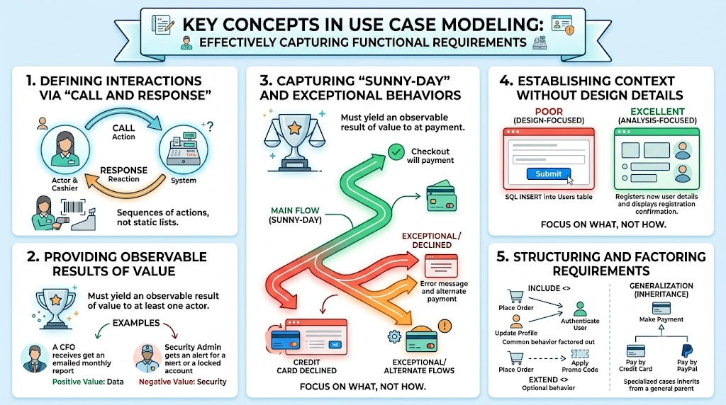
Functional requirements are not static lists of features; they are dynamic sequences of actions. Effective use case text must follow a "call and response" format. The actor initiates an action (the call), and the system reacts (the response). This ensures every system function is directly tied to a user's goal.
Example 1 (Retail):
Call: The Cashier scans the item's barcode.
Response: The system retrieves the item price, displays it on the screen, and adds it to the current transaction total.
Example 2 (Banking):
Call: The Account Holder requests a balance inquiry.
Response: The system fetches the current ledger balance and displays it on the ATM screen.
A critical rule of use case modeling is that every use case must yield an observable result of value to at least one actor. This prevents the modeling of trivial, internal system processes that do not benefit the user. The result must signify a definitive conclusion to the interaction, whether positive or negative.
Positive Value Example: "The system generates the monthly financial report and emails it to the CFO." (Value: The CFO receives necessary data).
Negative Value Example: "The system detects three consecutive failed login attempts, locks the user account, and sends a security alert to the administrator." (Value: The system protects itself from unauthorized access, providing security value to the admin).
Real-world systems rarely operate in a vacuum. Use cases capture the full scope of requirements by documenting multiple execution paths:
Main Flow (Sunny-Day Scenario): The ideal path where everything goes perfectly, and no errors occur.
Exceptional/Alternate Flows: The paths taken when errors occur, validations fail, or the user chooses a less frequent option.
Sunny-Day Example: A customer adds items to a cart, enters valid shipping details, and successfully pays with an approved credit card. The system confirms the order.
Exceptional Flow Example: During checkout, the credit card is declined. The system halts the main flow, displays an error message, and prompts the user to enter an alternative payment method (Alternate Course).
Use cases are an analysis tool, not a design tool. They describe what the system does, not how it does it. By deliberately avoiding implementation details (like UI colors, button placements, or database schemas), use cases keep the focus on business value and prevent premature technical constraints.
Poor (Design-focused): "The system displays a blue 'Submit' button in the top-right corner. When clicked, it executes an SQL INSERT statement into the Users database table."
Excellent (Analysis-focused): "The system registers the new user's details and displays a successful registration confirmation message."
As systems grow, use cases can become bloated. UML provides three specific relationships to structure, factor, and organize requirements efficiently:
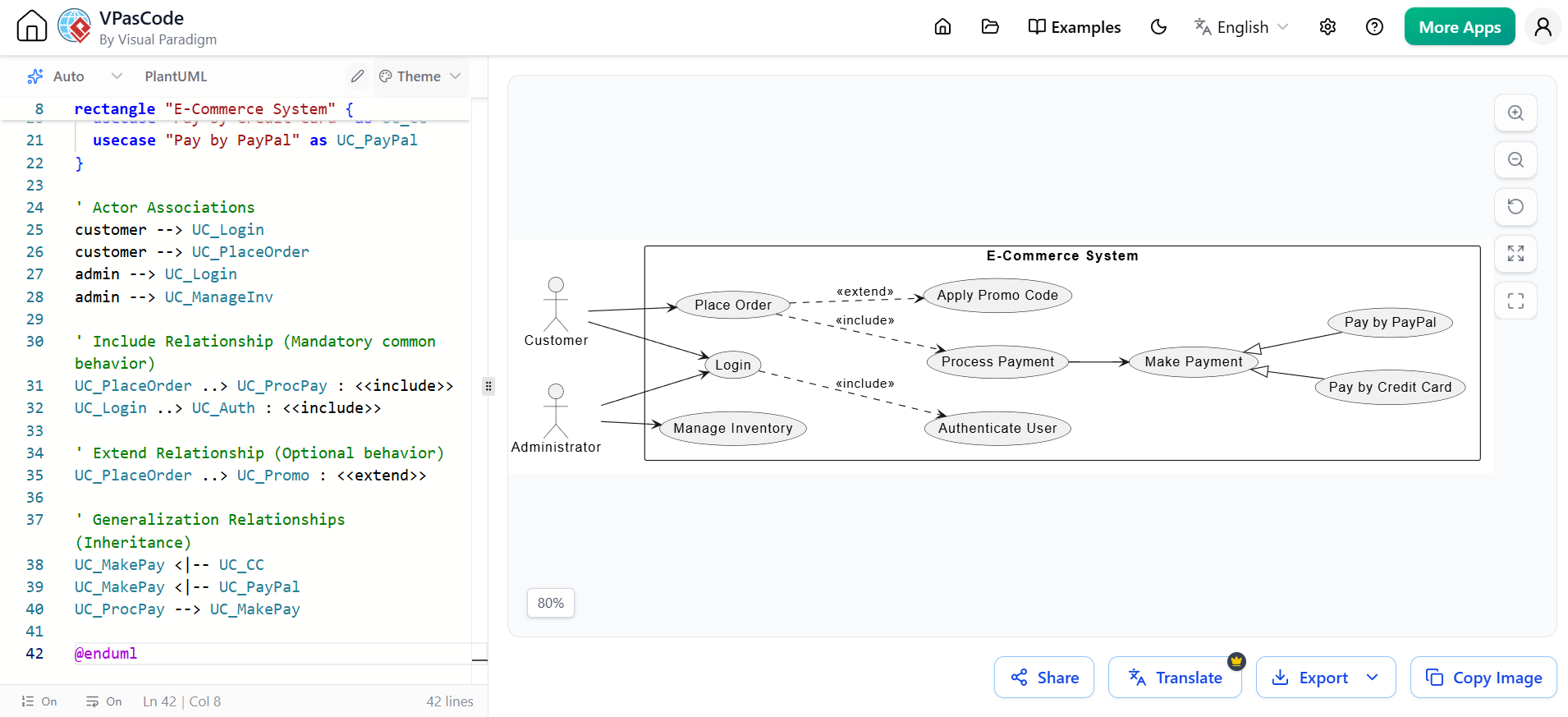
Include: Factors out mandatory, common behavior shared by multiple use cases to avoid redundancy.
Example: Both "Place Order" and "Update Profile" <> "Authenticate User".
Extend: Captures optional behavior or behavior that only executes under specific conditions.
Example: "Place Order" is <> by "Apply Promo Code" (the user only applies a code if they have one).
Generalization: Allows a specialized use case to inherit and override behavior from a general parent use case.
Example: "Make Payment" is the parent use case. "Pay by Credit Card" and "Pay by PayPal" are specialized child use cases that inherit the general payment flow but override the specific data collection steps.
Visualizing these concepts is crucial for stakeholder communication. Below are PlantUML examples demonstrating both the structural relationships and the behavioral "call and response" flows.
This diagram illustrates the structural factoring of requirements using Include, Extend, and Generalization within an E-Commerce system context.
@startuml
left to right direction
skinparam packageStyle rectangle

actor "Customer" as customer
actor "Administrator" as admin

rectangle "E-Commerce System" {

  ' Base Use Cases
  usecase "Login" as UC_Login
  usecase "Place Order" as UC_PlaceOrder
  usecase "Manage Inventory" as UC_ManageInv

  ' Factored / Specialized Use Cases
  usecase "Authenticate User" as UC_Auth
  usecase "Process Payment" as UC_ProcPay
  usecase "Apply Promo Code" as UC_Promo
  usecase "Make Payment" as UC_MakePay
  usecase "Pay by Credit Card" as UC_CC
  usecase "Pay by PayPal" as UC_PayPal
}

' Actor Associations
customer --> UC_Login
customer --> UC_PlaceOrder
admin --> UC_Login
admin --> UC_ManageInv

' Include Relationship (Mandatory common behavior)
UC_PlaceOrder ..> UC_ProcPay : <<include>>
UC_Login ..> UC_Auth : <<include>>

' Extend Relationship (Optional behavior)
UC_PlaceOrder ..> UC_Promo : <<extend>>

' Generalization Relationships (Inheritance)
UC_MakePay <|-- UC_CC
UC_MakePay <|-- UC_PayPal
UC_ProcPay --> UC_MakePay

@enduml
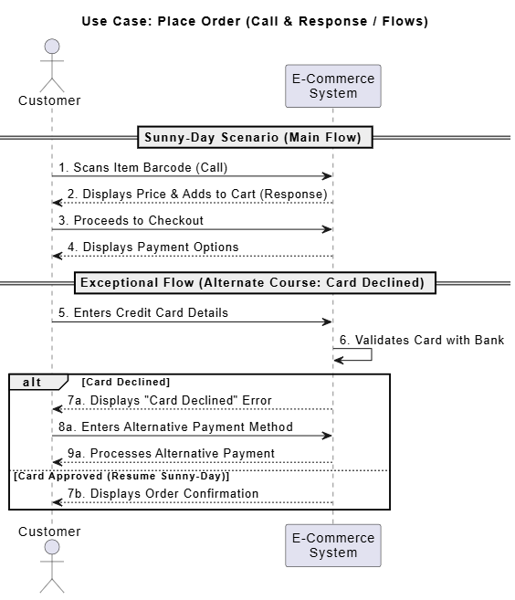
While Use Case diagrams show structure, Sequence diagrams are the perfect UML companion to illustrate the "Call and Response" mechanism and the transition from a Sunny-Day to an Exceptional Flow.
@startuml
actor Customer
participant "E-Commerce\nSystem" as System

title Use Case: Place Order (Call & Response / Flows)

== Sunny-Day Scenario (Main Flow) ==
Customer -> System: 1. Scans Item Barcode (Call)
System --> Customer: 2. Displays Price & Adds to Cart (Response)
Customer -> System: 3. Proceeds to Checkout
System --> Customer: 4. Displays Payment Options

== Exceptional Flow (Alternate Course: Card Declined) ==
Customer -> System: 5. Enters Credit Card Details
System -> System: 6. Validates Card with Bank
alt Card Declined
    System --> Customer: 7a. Displays "Card Declined" Error
    Customer -> System: 8a. Enters Alternative Payment Method
    System --> Customer: 9a. Processes Alternative Payment
else Card Approved (Resume Sunny-Day)
    System --> Customer: 7b. Displays Order Confirmation
end

@enduml
UML Use Cases are an indispensable tool in the software development lifecycle. By strictly adhering to the "call and response" format, ensuring every interaction yields an observable result of value, and meticulously mapping both sunny-day and exceptional flows, analysts can capture functional requirements with unparalleled clarity. Furthermore, by maintaining a strict boundary between analysis (the "what") and design (the "how"), and by leveraging UML's structuring relationships (<<include>>, <<extend>>, and Generalization), teams can manage complex requirements without overwhelming stakeholders.
To bring these concepts to life efficiently, utilizing robust modeling tooling is highly recommended. Visual Paradigm stands out as an premier tool for UML modeling. It offers an intuitive, drag-and-drop interface for creating complex Use Case diagrams, built-in support for PlantUML integration, and comprehensive templates for writing detailed use case specifications. By leveraging Visual Paradigm, business analysts and system architects can seamlessly collaborate, ensure requirement traceability, and accelerate the transition from functional analysis to successful system design.

