In the complex world of software development, understanding what a system should do is just as critical as knowing how it should do it. Use case diagrams serve as a powerful bridge between stakeholders and development teams, offering a visual representation of system behavior from an external perspective.
This tutorial explores the fundamental concepts of use case modeling, demonstrating how to effectively capture requirements through actors, use cases, and their relationships. By mastering these techniques, product managers, business analysts, and developers can ensure clear communication and alignment throughout the project lifecycle.
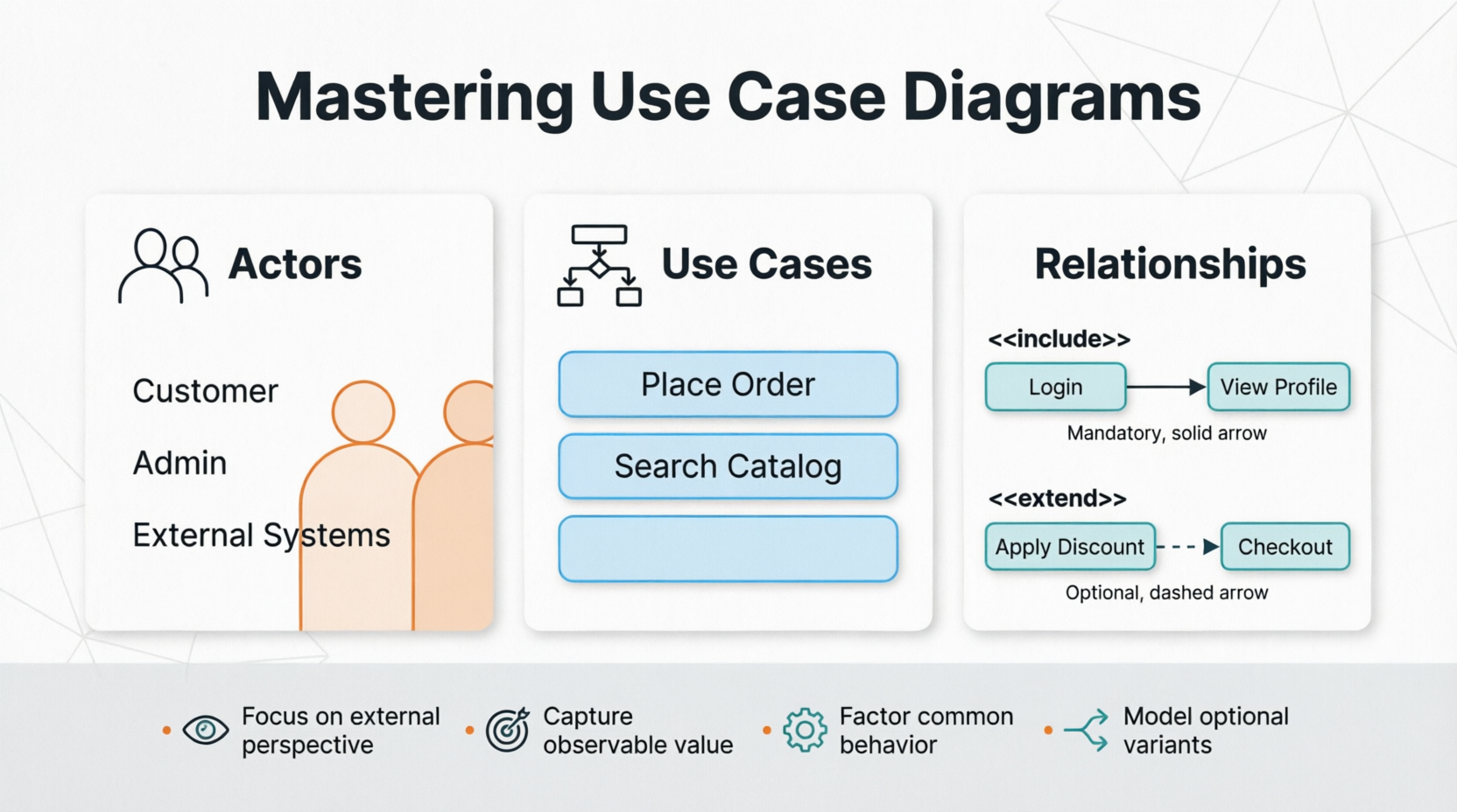
Actors represent roles that users or other systems play when interacting with your application. They are not necessarily individual people but rather the hats that different entities wear when engaging with the system. For example, in an e-commerce platform, you might have actors such as:
Customer: Browses products, places orders
Administrator: Manages inventory, processes returns
Payment Gateway: External system that processes transactions
Shipping Service: External system that handles logistics
Each actor has specific goals and interacts with the system in distinct ways. Identifying all relevant actors early in the process ensures comprehensive requirement coverage.
A use case describes a sequence of actions that provide measurable value to an actor. Each use case should:
Have a clear goal from the actor's perspective
Result in an observable outcome
Represent a complete piece of functionality
For instance, "Place Order" is a use case because it delivers tangible value to the Customer actor. In contrast, "Validate Credit Card" might be too granular—it's better represented as part of a larger use case or through an include relationship.
Understanding relationships between use cases is crucial for creating maintainable and scalable diagrams:
Include Relationship (<>)
Factors out common behavior shared across multiple use cases
The base use case always includes the included use case
Example: Both "Place Order" and "Update Profile" might <> "Authenticate User"
Extend Relationship (<>)
Represents optional or conditional behavior
The extending use case adds functionality under specific conditions
Example: "Apply Discount Code" might <> "Place Order" only when a customer has a valid code
These relationships help avoid duplication and make your diagrams more modular and easier to understand.
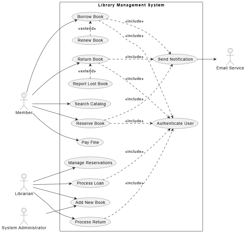
Let's walk through creating a use case diagram for an online library management system.
Member: Borrows books, reserves items, pays fines
Librarian: Manages catalog, processes loans, handles returns
System Administrator: Manages user accounts, configures system settings
Email Service: Sends notifications (external system)
For the Member actor:
Search Catalog
Borrow Book
Return Book
Reserve Book
Pay Fine
For the Librarian actor:
Add New Book
Process Loan
Process Return
Manage Reservations
Common behaviors that should be factored out:
"Authenticate User" is <> by most member and librarian actions
"Send Notification" is <> by actions like "Borrow Book" and "Return Book"
Optional behaviors:
"Renew Book" <> "Borrow Book" when the member wants to extend the loan period
"Report Lost Book" <> "Return Book" when a book cannot be located
@startuml
left to right direction

actor Member
actor Librarian
actor "System Administrator" as Admin
actor "Email Service" as Email

rectangle "Library Management System" {

  usecase "Search Catalog" as UC1
  usecase "Borrow Book" as UC2
  usecase "Return Book" as UC3
  usecase "Reserve Book" as UC4
  usecase "Pay Fine" as UC5
  usecase "Add New Book" as UC6
  usecase "Process Loan" as UC7
  usecase "Process Return" as UC8
  usecase "Manage Reservations" as UC9
  usecase "Authenticate User" as UC10
  usecase "Send Notification" as UC11
  usecase "Renew Book" as UC12
  usecase "Report Lost Book" as UC13

}

Member --> UC1
Member --> UC2
Member --> UC3
Member --> UC4
Member --> UC5

Librarian --> UC6
Librarian --> UC7
Librarian --> UC8
Librarian --> UC9

Admin --> UC6

UC2 ..> UC10 : <<include>>
UC3 ..> UC10 : <<include>>
UC4 ..> UC10 : <<include>>
UC7 ..> UC10 : <<include>>
UC8 ..> UC10 : <<include>>

UC2 ..> UC11 : <<include>>
UC3 ..> UC11 : <<include>>
UC4 ..> UC11 : <<include>>

UC12 .> UC2 : <<extend>>
UC13 .> UC3 : <<extend>>

UC11 --> Email

@enduml
This diagram clearly shows:
Which actors interact with which use cases
Common functionality factored out through include relationships
Optional behaviors captured through extend relationships
External system interactions (Email Service)
Start with high-level use cases before diving into details. Avoid creating overly complex diagrams that try to capture every edge case.
Each use case should deliver observable value to an actor. If you can't articulate the value, reconsider whether it belongs as a separate use case.
Name use cases from the actor's perspective using verb-noun combinations: "Place Order," not "Order Processing Module."
A single diagram should focus on a coherent subset of functionality. For large systems, create multiple diagrams organized by module or actor group.
Review diagrams with actual users and stakeholders to ensure they accurately represent real-world scenarios and expectations.
Use professional tools like Visual Paradigm to create, maintain, and share your diagrams. These platforms offer features for collaboration, version control, and integration with other modeling artifacts.
Confusing Include and Extend
Remember: Include is mandatory; Extend is optional
Ask: "Does this always happen?" → Include
Ask: "Does this happen sometimes?" → Extend
Over-Granular Use Cases
Breaking down use cases too finely creates maintenance overhead
Keep use cases at a level that represents complete user goals
Ignoring External Systems
Don't forget to model interactions with external APIs, services, or legacy systems as actors
Mixing Implementation Details
Use case diagrams should capture what the system does, not how it does it
Save technical implementation details for other design artifacts
Use case diagrams are invaluable tools for capturing system requirements from an external perspective. By clearly identifying actors, defining meaningful use cases, and properly modeling relationships through include and extend connections, teams can establish a shared understanding of system behavior early in the development process.
The key to success lies in balancing completeness with simplicity—capturing enough detail to guide development while maintaining clarity for all stakeholders. With practice and adherence to best practices, use case modeling becomes an essential skill in any product manager's or business analyst's toolkit.
As you apply these concepts to your own projects, remember that use case diagrams are living documents. They should evolve alongside your understanding of user needs and system capabilities. Regular refinement and validation with stakeholders will ensure your diagrams remain accurate and valuable throughout the project lifecycle.
Whether you're working on a small feature or a large-scale enterprise system, mastering use case diagrams will enhance your ability to communicate requirements effectively and build solutions that truly deliver value to users.