While class diagrams provide the static skeleton of a software system, they cannot tell the whole story. Software is inherently dynamic; it is defined by what happens when users interact with it and how components communicate over time. To truly understand system behavior, architects and developers must visualize the temporal flow of interactions. This is the domain of Sequence Diagrams.
Sequence diagrams are a type of interaction diagram in UML that focuses on the message exchange between objects arranged in chronological order. They are essential for validating use cases, designing complex APIs, debugging distributed systems, and ensuring that all stakeholders share a common understanding of runtime logic. In this tutorial, we will explore the fundamental mechanics of sequence diagrams, demonstrate their creation using PlantUML, and examine how professional platforms like Visual Paradigm can elevate your behavioral modeling capabilities.
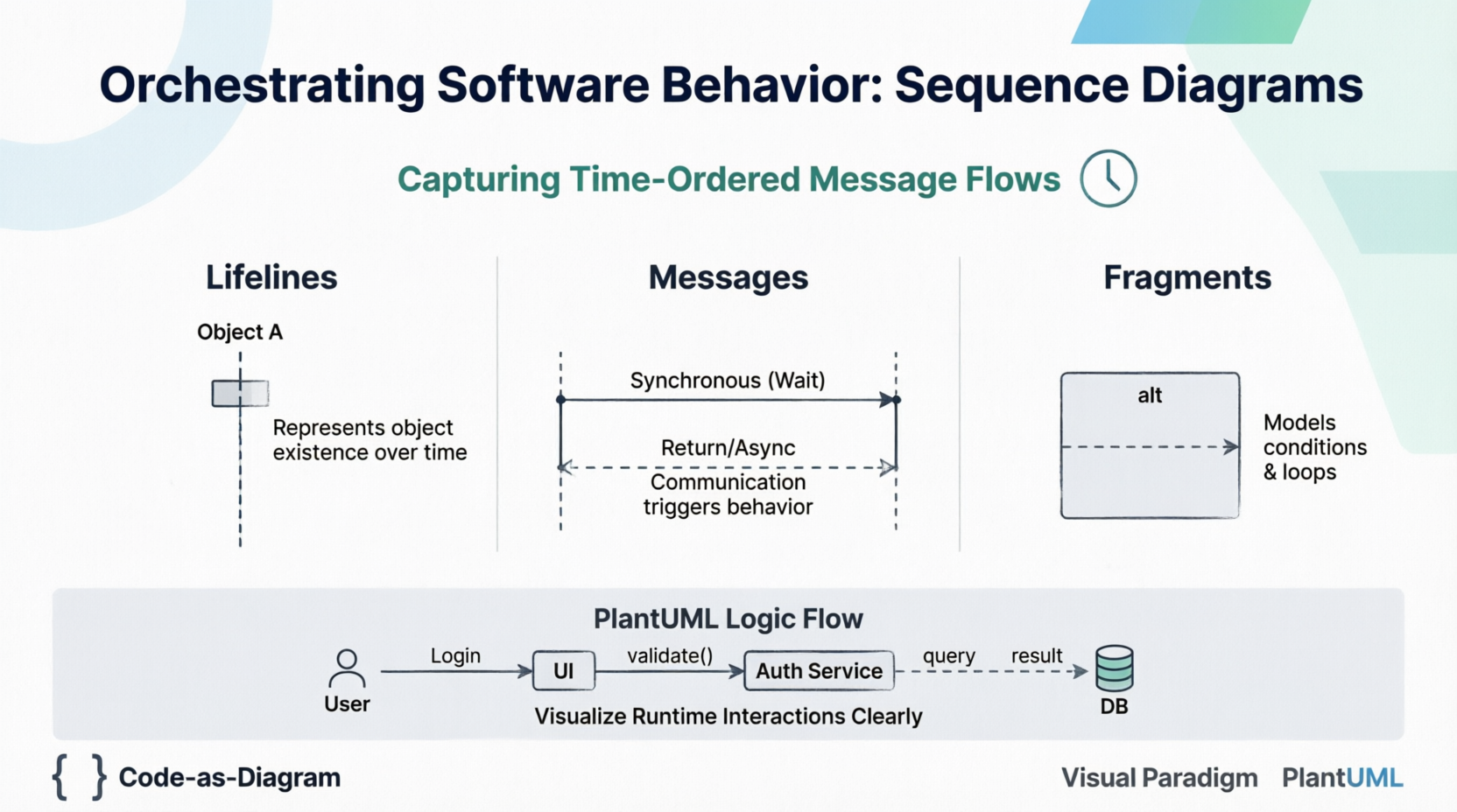
A Lifeline represents the existence of an object or participant during a specific period of interaction. Visually, it is depicted as a rectangle containing the object's name (often underlined) with a dashed vertical line extending downward. This vertical axis represents time, flowing from top to bottom.
Messages are the arrows connecting lifelines, representing communication that triggers behavior. The style of the arrow dictates the nature of the communication:
->): A solid line with a filled arrowhead. The sender waits for the receiver to complete the operation before proceeding. This models standard method calls.-->): A solid line with an open arrowhead. The sender continues immediately without waiting for a response. This is crucial for modeling event-driven architectures, callbacks, and multi-threaded systems.<--): A dashed line with an open arrowhead indicating the flow of control returning to the caller, often carrying a return value.Real-world logic involves conditions and loops. Interaction Fragments allow you to model these complexities directly on the diagram:
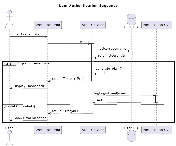
PlantUML allows you to define sequence diagrams as code, making them version-controllable and easy to maintain. Below is a comprehensive example modeling a secure user login process, incorporating synchronous calls, asynchronous notifications, and conditional logic.
PlantUML Example:
@startuml
title User Authentication Sequence

actor User
participant "Web Frontend" as UI
participant "Auth Service" as Auth
database "User DB" as DB
participant "Notification Svc" as Notify

' Initial Request
User -> UI : Enter Credentials
UI -> Auth : authenticate(user, pass)

activate Auth
Auth -> DB : findUser(username)
activate DB
DB --> Auth : return UserEntity
deactivate DB

alt Valid Credentials
    Auth -> Auth : generateToken()
    Auth --> UI : return Token + Profile
    deactivate Auth

    UI --> User : Display Dashboard

    ' Async side-effect
    Auth --> Notify : logLoginEvent(userId)
    activate Notify
    Notify --> Auth : Ack
    deactivate Notify

else Invalid Credentials
    Auth --> UI : return Error(401)
    deactivate Auth
    UI --> User : Show Error Message
end

@enduml
This script generates a clear visualization of the authentication flow, distinguishing between the critical path (returning the token) and non-blocking side effects (logging the event).
For enterprise-grade modeling, the Visual Paradigm ecosystem offers advanced capabilities beyond text-based generation. While PlantUML excels at speed and documentation-as-code, Visual Paradigm provides a robust GUI environment tailored for complex architectural analysis.
alt or opt fragments, write boolean conditions that are unambiguous (e.g., [balance > 0] rather than just [check]).Sequence diagrams bridge the gap between abstract requirements and concrete implementation. By visualizing the time-ordered flow of messages, teams can identify bottlenecks, validate race conditions, and ensure that distributed components interact correctly before writing production code. Whether you leverage the agility of PlantUML for documentation or the analytical power of Visual Paradigm for deep system design, mastering sequence diagrams is a critical skill for modern software engineering.
As systems become increasingly asynchronous and distributed, the ability to clearly articulate "who talks to whom, when, and why" becomes not just a documentation exercise, but a fundamental engineering discipline. Start small with simple login flows or data retrieval scenarios, and gradually apply these techniques to map out the complex choreography of your software architecture.