
In modern software engineering, capturing the dynamic behavior of a system is just as critical as defining its static structure. While class diagrams outline relationships and data, they fall short of illustrating how components interact over time to fulfill business requirements. UML Sequence Diagrams bridge this gap by modeling message exchanges in chronological order, making them indispensable for analyzing use cases, validating system workflows, and guiding implementation.
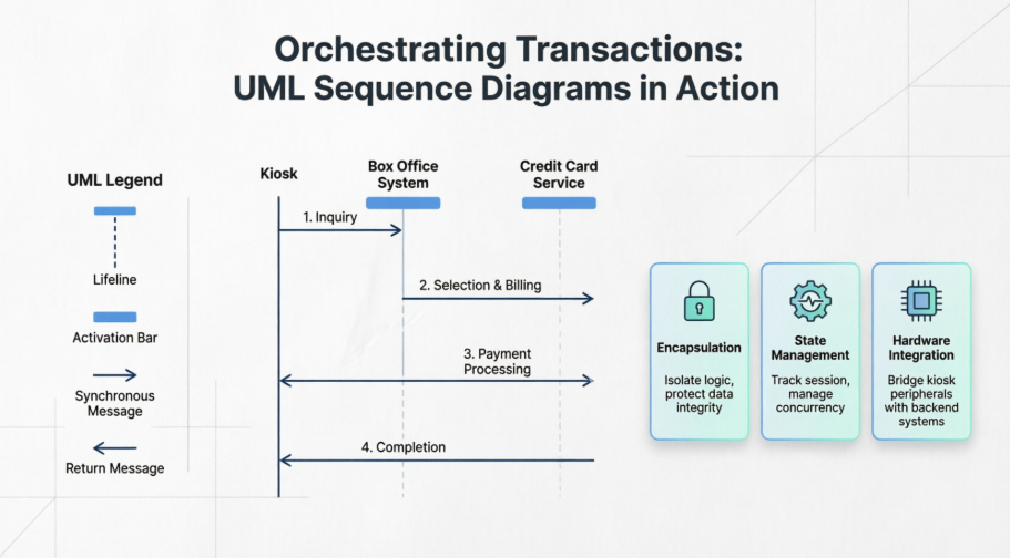
This case study examines the design of an Automated Ticket Purchase System through the lens of a UML sequence diagram. By mapping a single, complete transaction scenario, we explore how sequence diagrams clarify system responsibilities, enforce architectural boundaries, and translate high-level use cases into actionable development artifacts. The analysis highlights key UML notation, architectural decisions, and the practical considerations that emerge when modeling real-world hardware-software integrations.
The Automated Ticket Purchase System comprises three primary components:
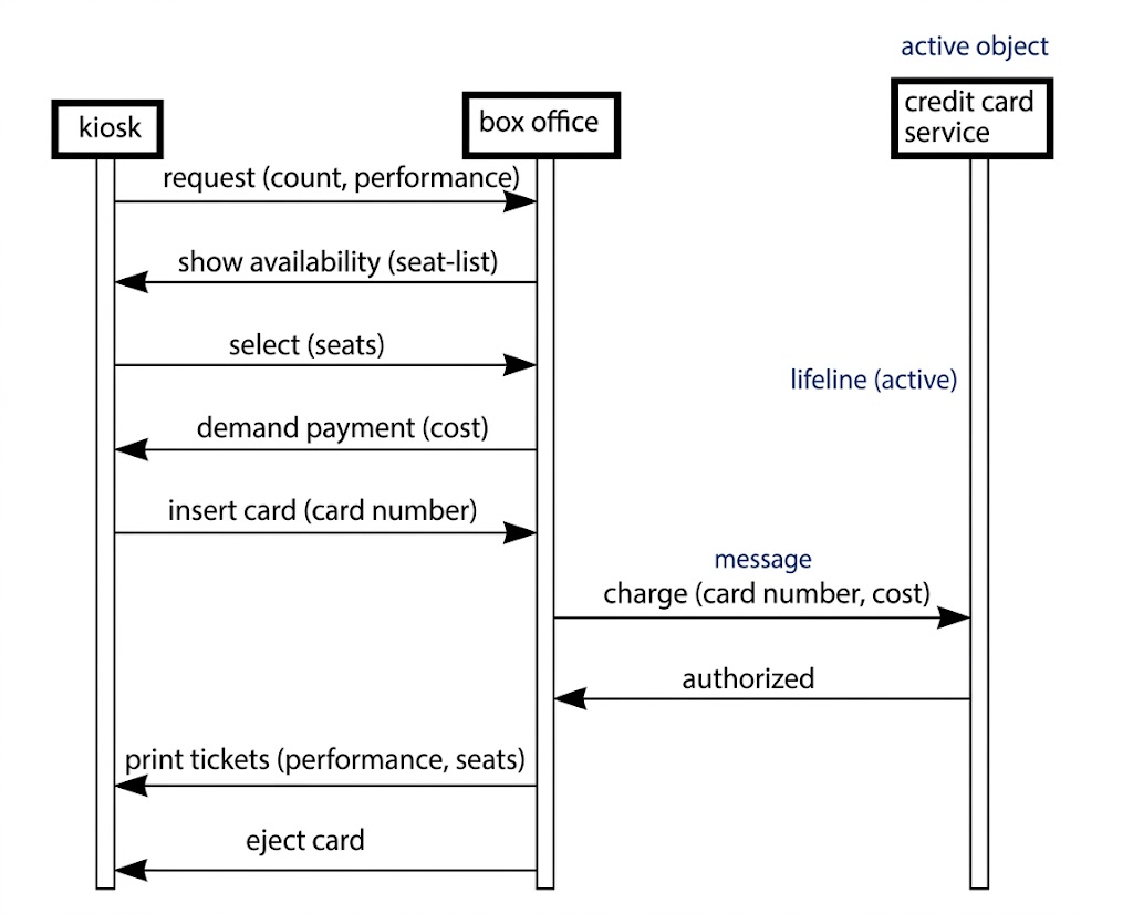
Kiosk: A user-facing hardware/software terminal that captures customer input, displays seat availability, processes card insertion, and prints physical tickets.
Box Office System: The central logic controller responsible for inventory management, pricing, transaction coordination, and state persistence.
Credit Card Service: An external, third-party payment gateway that handles authorization, fraud checks, and financial settlement.
The system is designed around the "Buy Tickets" use case, initiated when a customer approaches the kiosk to purchase tickets for a specific performance. The sequence diagram models a successful transaction path, illustrating how these distributed components collaborate while maintaining clear separation of concerns.
The sequence diagram captures a linear, time-ordered narrative of a single customer transaction:
| Phase | Interaction Flow | System Response |
|---|---|---|
| 1. Inquiry | Kiosk sends requestAvailability(performanceID, count) |
Box Office queries inventory and returns showAvailability(seat-list) |
| 2. Selection & Billing | Customer selects seats via kiosk UI; Box Office calculates total and triggers demandPayment(cost) |
Kiosk prompts user to insert/swipe card |
| 3. Payment Processing | Kiosk captures cardNumber and forwards to Box Office; Box Office delegates charge(amount, cardNumber) to Credit Card Service |
External service validates and returns authorized(status) |
| 4. Completion | Upon authorization, Box Office sends printTickets(seat-list) and ejectCard() to Kiosk |
Kiosk dispenses tickets, releases card, and resets UI for next user |
This walkthrough demonstrates a tightly orchestrated workflow where each step depends on the successful completion of the previous one, highlighting the critical role of synchronous communication in transactional systems.
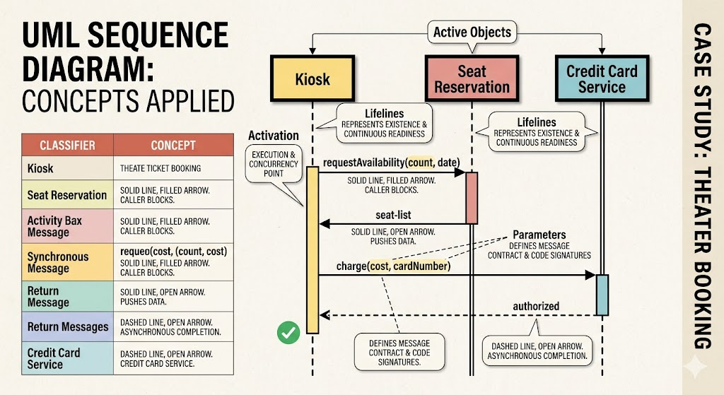
The diagram leverages foundational UML notation to convey temporal and structural semantics:
| Concept | Visual Representation | Role in This Case Study |
|---|---|---|
| Lifeline | Vertical dashed/double line | Represents each participant's existence over the duration of the transaction. The double-line style emphasizes continuous readiness to process messages. |
| Active Object | Bold-bordered classifier box (Kiosk, Credit Card Service) | Denotes objects with independent threads of control. The Credit Card Service, for example, operates asynchronously from the box office once invoked. |
| Activation Bar | Narrow vertical rectangle on a lifeline | Highlights the exact time window an object is executing an operation or waiting for a response. Overlapping bars reveal concurrency points. |
| Synchronous Message | Solid line with filled arrowhead (►) |
Used for requestAvailability, charge, and demandPayment. Indicates the caller blocks until a reply is received. |
| Return Message | Solid/dashed line with open arrowhead (◄) |
Carries response payloads (seat-list, authorized). Ensures data flows back to the initiator for next-step processing. |
| Parameters | Text in parentheses ( ) |
Explicitly defines the contract of each message (e.g., count, cost, cardNumber), bridging design and code signatures. |
The kiosk never communicates directly with the credit card service. The box office acts as a strict mediator, enforcing business rules: payment is only requested after seat selection, and ticket issuance is gated behind payment authorization. This decoupling improves security, simplifies audit trails, and allows the payment gateway to be swapped without modifying kiosk logic.
Sequence diagrams inherently imply state. The box office must temporarily persist selected seats, calculated costs, and transaction IDs while awaiting the credit card service's response. This observation prompts developers to consider session management, timeout handling, and rollback strategies in case of network failures or declined transactions.
Unlike purely software-focused diagrams, this model includes physical interaction commands (printTickets, ejectCard). This bridges the gap between abstract business logic and tangible user experience, reminding engineers that backend transactions ultimately drive hardware actuators, card readers, and printers.
While this diagram represents an early-stage design, it provides a direct blueprint for development:
Message-to-Code Mapping: Each arrow corresponds to a method signature or event trigger. charge(amount, cardNumber) becomes a service interface call, while authorized(status) maps to a callback or response handler.
Testing Strategy: The linear scenario serves as a primary test case for integration testing. QA teams can mock the credit card service to simulate success, decline, and timeout conditions.
Iterative Refinement: As noted in the original design, UI specifics (seat selection mechanics, list formatting) remain undefined. Subsequent iterations will add alt/opt fragments to handle edge cases: insufficient seats, payment retries, network drops, and user cancellations.
UML sequence diagrams are more than visual aids; they are executable blueprints that translate abstract use cases into precise, time-bound interactions. In this Automated Ticket Purchase System case study, the sequence diagram successfully clarifies component responsibilities, enforces secure transaction boundaries, and exposes hidden design considerations like state persistence and hardware coordination.
By modeling a single successful scenario, development teams gain a shared understanding of system behavior before writing a single line of code. As the design matures, this foundational diagram will expand to include error handling, concurrency, and alternative flows, ultimately serving as a living artifact that guides architecture, implementation, and testing. In complex, multi-tier systems where timing and order dictate success, sequence diagrams remain an indispensable tool for orchestrating reliable, user-centric transactions.

