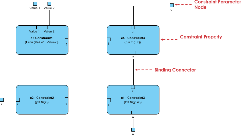
A parametric diagram is defined as a restricted form of an internal block diagram. A parametric diagram may contain constraint properties and their parameters, along with other properties from within the internal block context. All properties that appear, other than the constraints themselves, must either be bound directly to a constraint parameter or contain a property that is bound to one (through any number of levels of containment).
Constraint blocks provide a mechanism for integrating engineering analysis such as performance and reliability models with other SysML models. Constraint blocks can be used to specify a network of constraints that represent mathematical expressions such as {F=m*a} and {a=dv/dt}, which constrain the physical properties of a system. Such constraints can also be used to identify critical performance parameters and their relationships to other parameters, which can be tracked throughout the system life cycle.
A constraint block includes the constraint, such as {F=m*a}, and the parameters of the constraint such as F, m, and a. Such constraints can be arbitrarily complex mathematical or logical expressions.
Constraint blocks define generic forms of constraints that can be used in multiple contexts.
Parametric diagrams include usages of constraint blocks to constrain the properties of another block. The usage of a constraint binds the parameters of the constraint, such as F, m, and a, to specific properties of a block, such as a mass, that provide values for the parameters.
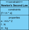
The example in Figure below defines a constraint block called ‘Newton’s Second Law’ that relates the three parameters ‘f’, ‘m’ and ‘a’ given in the parameters compartment by the equation ‘f = m * a’, as shown in the constraints compartment.
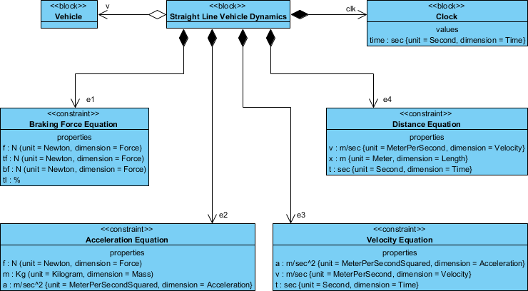
SysML allows you to define parametric relationships between the properties of blocks. The relations between the properties of different blocks can be described and defined in a parametric diagram. The constraints form a network across all properties of the blocks.
The parametric diagram represents constraints on System property values, allowing engineering analysis models to be produced as well as defining complex constraint relationships that can be used in verification and validation of activities. A parametric diagram is uniquely capable of conveying these mathematical models to stakeholders.
Parametric diagrams are made up of the following elements:
Parametric Diagrams can be created for Item Flows that bind flow parameters to Constraint parameters.
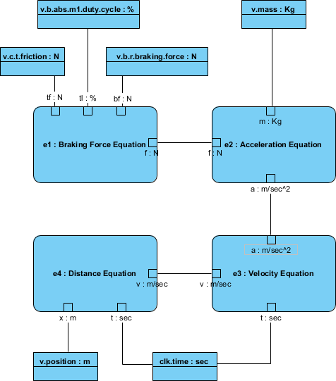
In the figure below, properties of the vehicle are bound to the parameters of the equations used to analyze vehicle stopping distance. Parametric models thus help identify the properties of the system that are critical to satisfying requirements. The Parametric diagram depicts a network of equations that constrain the properties of blocks. The properties of the system are bound to the parameters of the analysis equations (e.g. vehicle mass is bound to 'm’ in F=m x a)
Parametric diagrams are used to create systems of equations that can constrain the properties of blocks. The complete header for a parametric diagram is as follows:
par [model element type] model element name [diagram name]
The diagram kind is par, and the model element type can be either a block or a constraint block.