
As software systems evolve from simple scripts into massive, interconnected ecosystems comprising hundreds or thousands of components, the sheer volume of code can become overwhelming. How do development teams keep track of every part’s responsibilities? How do they ensure the final product actually meets customer requirements without getting lost in the weeds of source code?
The answer lies in the Unified Modeling Language (UML).
UML is not a programming language; rather, it is a formal, standardized visual language used to abstract, visualize, document, and communicate the critical aspects of a system. This comprehensive guide will walk beginners through the core concepts of UML, demonstrate how it manages complexity, and provide realistic, code-based examples to help you start modeling like a pro.
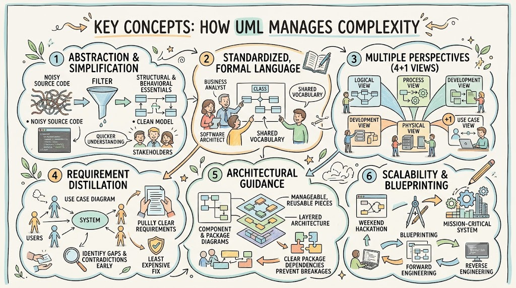
UML aids in managing system complexity through several foundational mechanisms. Understanding these concepts is the first step to mastering system design.
A UML model acts as a filter. It removes the irrelevant, syntactic noise found in raw source code. By focusing only on the structural and behavioral essentials, stakeholders can understand, evaluate, and criticize the design and viability of a system much faster than if they had to read thousands of lines of code.
Unlike informal whiteboard sketches or ambiguous natural language, UML provides a strongly defined meaning for every element. A "class" or a "dependency" means the exact same thing to a business analyst, a software architect, and a junior developer. This shared vocabulary eliminates costly misunderstandings.
Complex systems cannot be understood from a single angle. UML manages complexity by breaking the system into different "views":
Logical View: Describes the system's internal parts (classes/objects) and their interactions.
Process View: Models the workflows, concurrency, and performance aspects of the system.
Development View: Organizes parts into modules, libraries, and components for the development team.
Physical View: Shows how the software is deployed onto the actual hardware infrastructure.
(The "+1" is the Use Case View, which bridges the gap by describing external requirements).
Before writing code, teams must know what to build. UML Use Case diagrams specify exactly what a system is supposed to do from an external user's perspective. This helps identify gaps or contradictions in requirements early in the project lifecycle, when they are least expensive to fix.
Diagrams like Component and Package diagrams allow designers to organize a system into manageable, reusable, and swappable pieces. This helps manage the layers within a system’s architecture and maintain stability by clearly identifying package dependencies (ensuring changes in one module don't break another).
UML is formal enough to handle massive modeling projects for mission-critical industries (like defense or medical systems), yet concise enough to scale down for a weekend hackathon. By using UML as a blueprint, teams can synchronize their design with code through forward engineering (generating code from diagrams) and reverse engineering (generating diagrams from existing code), ensuring the design remains accurate as the system evolves.
To see these concepts in action, let's design a realistic system: A Smart Hospital Patient Monitoring System. This system collects vitals from patient wearables, processes the data, and alerts medical staff if anomalies are detected.
Below are the PlantUML codes for the key diagrams. You can copy and paste these into any PlantUML renderer to see the visual output.
This diagram captures the Logical/Use Case View. It distills complex requirements into simple interactions between the actors (users) and the system.
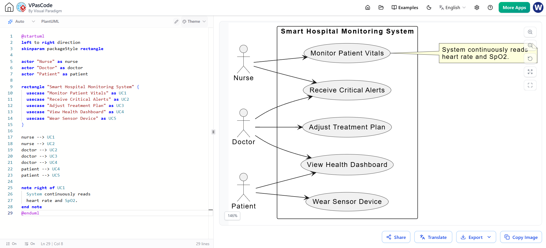
@startuml
left to right direction
skinparam packageStyle rectangle

actor "Nurse" as nurse
actor "Doctor" as doctor
actor "Patient" as patient

rectangle "Smart Hospital Monitoring System" {
  usecase "Monitor Patient Vitals" as UC1
  usecase "Receive Critical Alerts" as UC2
  usecase "Adjust Treatment Plan" as UC3
  usecase "View Health Dashboard" as UC4
  usecase "Wear Sensor Device" as UC5
}

nurse --> UC1
nurse --> UC2
doctor --> UC2
doctor --> UC3
doctor --> UC4
patient --> UC4
patient --> UC5

note right of UC1
  System continuously reads
  heart rate and SpO2.
end note
@enduml
This diagram represents the Development View. It uses packages to group related components, ensuring high cohesion and low coupling (the golden rules of software architecture).
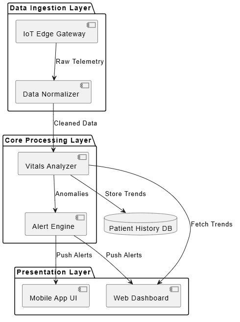
@startuml
skinparam componentStyle uml2

package "Data Ingestion Layer" {
  [IoT Edge Gateway] as GW
  [Data Normalizer] as DN
}

package "Core Processing Layer" {
  [Vitals Analyzer] as VA
  [Alert Engine] as AE
}

package "Presentation Layer" {
  [Mobile App UI] as UI
  [Web Dashboard] as WD
}

database "Patient History DB" as DB

' Dependencies
GW --> DN : Raw Telemetry
DN --> VA : Cleaned Data
VA --> AE : Anomalies
VA --> DB : Store Trends
AE --> UI : Push Alerts
AE --> WD : Push Alerts
VA --> WD : Fetch Trends
@enduml
This diagram shows the Physical View, mapping the software components from the previous diagram onto the actual hardware and network infrastructure.
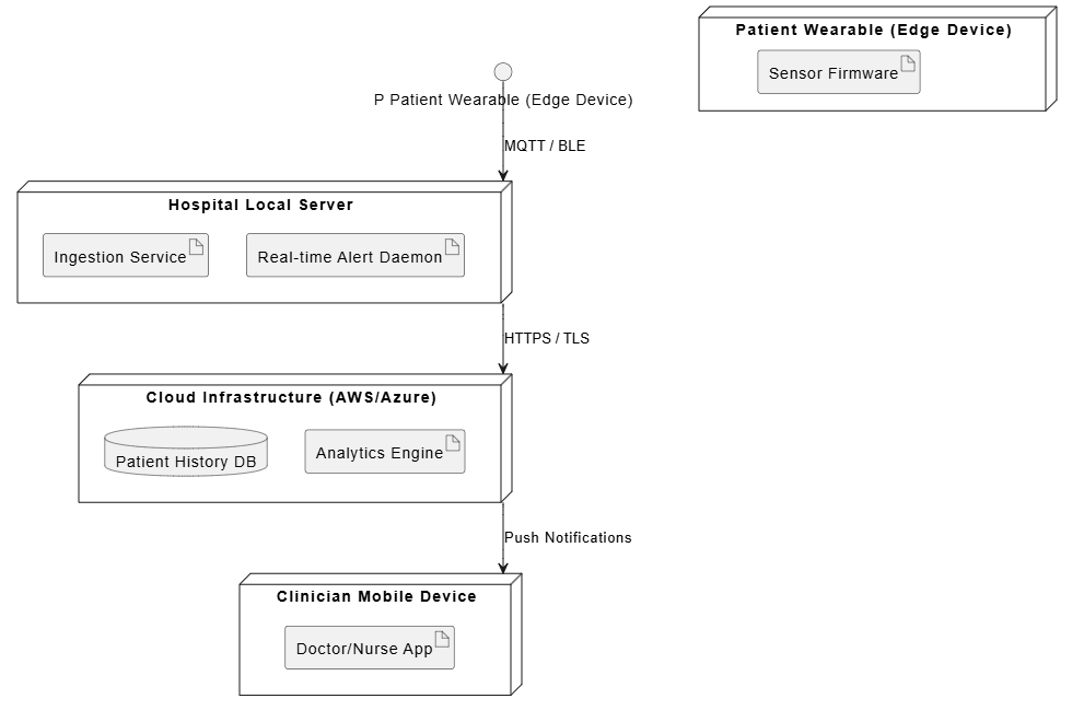
@startuml
node "Patient Wearable (Edge Device)" {
  artifact "Sensor Firmware"
}

node "Hospital Local Server" {
  artifact "Ingestion Service"
  artifact "Real-time Alert Daemon"
}

node "Cloud Infrastructure (AWS/Azure)" {
  database "Patient History DB"
  artifact "Analytics Engine"
}

node "Clinician Mobile Device" {
  artifact "Doctor/Nurse App"
}

' Network Connections
"P Patient Wearable (Edge Device)" --> "Hospital Local Server" : MQTT / BLE
"Hospital Local Server" --> "Cloud Infrastructure (AWS/Azure)" : HTTPS / TLS
"Cloud Infrastructure (AWS/Azure)" --> "Clinician Mobile Device" : Push Notifications
@enduml
While you can write PlantUML in plain text, beginners and professionals alike benefit immensely from Graphical User Interface (GUI) tools. For this guide, we highly recommend Visual Paradigm.
Visual Paradigm is an industry-standard, comprehensive UML tool that supports all diagram types, offers robust code engineering (forward/reverse), and provides enterprise-level collaboration features.
Modern versions of Visual Paradigm integrate powerful AI-assisted features that drastically reduce the learning curve for beginners and speed up workflow for experts:
AI-Powered Text-to-Diagram: You can simply type a natural language prompt (e.g., "Create a use case diagram for a library management system with admins and members"), and the AI will instantly generate the foundational UML diagram for you to refine.
Smart Layout & Formatting: AI algorithms automatically arrange and route diagram elements to prevent overlapping lines and ensure the diagram is visually clean and professional, saving hours of manual dragging and dropping.
AI Code Generation & Refactoring: Beyond standard forward engineering, the AI can suggest optimal code structures based on your UML models, or analyze existing code to suggest architectural improvements before reverse-engineering it into a diagram.
Intelligent Autocomplete: As you draw relationships or add properties to classes, the AI suggests standard naming conventions and logical relationship types based on the context of your model.
Managing the complexity of modern software systems is one of the greatest challenges in technology today. Without a structured approach, projects easily succumb to scope creep, miscommunication, and architectural decay.
The Unified Modeling Language (UML) solves this by providing a formal, standardized blueprint. Through abstraction, multiple architectural views, and rigorous requirement distillation, UML allows teams to visualize the forest without getting lost in the trees. Whether you are designing a small mobile app or a mission-critical medical monitoring system, mastering UML equips you with the vocabulary and the visual tools to design, communicate, and build software that stands the test of time.
By leveraging modern tools like Visual Paradigm and its AI capabilities, the barrier to entry has never been lower. Start small, model your next project's requirements with a Use Case diagram, and watch your system's complexity transform from a chaotic hurdle into a manageable, well-architected blueprint.

