
When modeling complex systems using the Unified Modeling Language (UML), one of the most critical decisions an architect or business analyst must make is the perspective from which the system is viewed. A common pitfall in system design is conflating what a system does for its users with how the system achieves those functions internally.
To resolve this, UML divides system modeling into two distinct perspectives: the External View and the Internal View. The external view treats the system as a "black box," focusing purely on user interactions and observable value. Conversely, the internal view opens that box, revealing the "white box" mechanics of internal structures, workflows, and object collaborations.
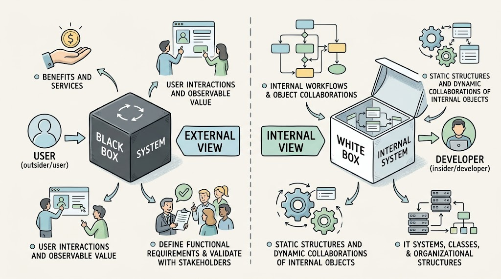
This guide provides a comprehensive breakdown of these two views, exploring their conceptual differences, their application in both business and IT contexts, and practical PlantUML examples to illustrate how they are modeled in the real world.
The fundamental divide between the external and internal views lies in their perspective, visibility, focus, and primary goals.
| Feature | External View | Internal View |
|---|---|---|
| Perspective | Outsider/User: Perceived by external actors (customers, partners, end-users). | Insider/Developer: How functionality is designed and executed inside the system. |
| System Visibility | Black Box: Internal transactions, logic, and structures are irrelevant and hidden. | White Box: Reveals internal workflows, IT systems, classes, and organizational structures. |
| Focus | Benefits and Services: What goods or services are offered and how users interact with them. | Implementation: How internal resources (workers, objects, classes) provide those services. |
| Primary Goal | Define functional requirements and validate them with stakeholders. | Define the static structures and dynamic collaborations of internal objects. |
In the realm of business architecture, the distinction between these views dictates how processes and organizational roles are mapped.
The Business External View: This view is strictly from the role of a customer or supplier. It focuses on business use cases that provide observable, measurable value to the outside world. Modelers use high-level activity and sequence diagrams to show interactions between external actors and the business environment, completely ignoring internal departmental boundaries.
The Business Internal View: This view opens the organization to describe internal business processes and organizational structures. It introduces package diagrams to model organizational units (departments, teams) and class diagrams to model relationships between internal workers and business objects. Crucially, the internal view accounts for how work is done—identifying whether a process is manual or IT-supported, and pinpointing the specific workers responsible for actions.
For software and IT systems, the views separate user experience from software architecture.
The IT External View (User View): This captures requirements from the perspective of a user sitting in front of a keyboard or using a mobile device. It describes system behavior exactly as the user perceives it through use case diagrams and interface prototypes. In this view, information is exchanged via "query events" (reading data, like checking a balance) and "mutation events" (modifying data, like transferring funds) without revealing which internal database tables or objects are actually affected.
The IT Internal View: This is the blueprint for the development team, broken down into three sub-views:
Structural: Uses class diagrams to show the internal static structures (attributes, methods, and associations).
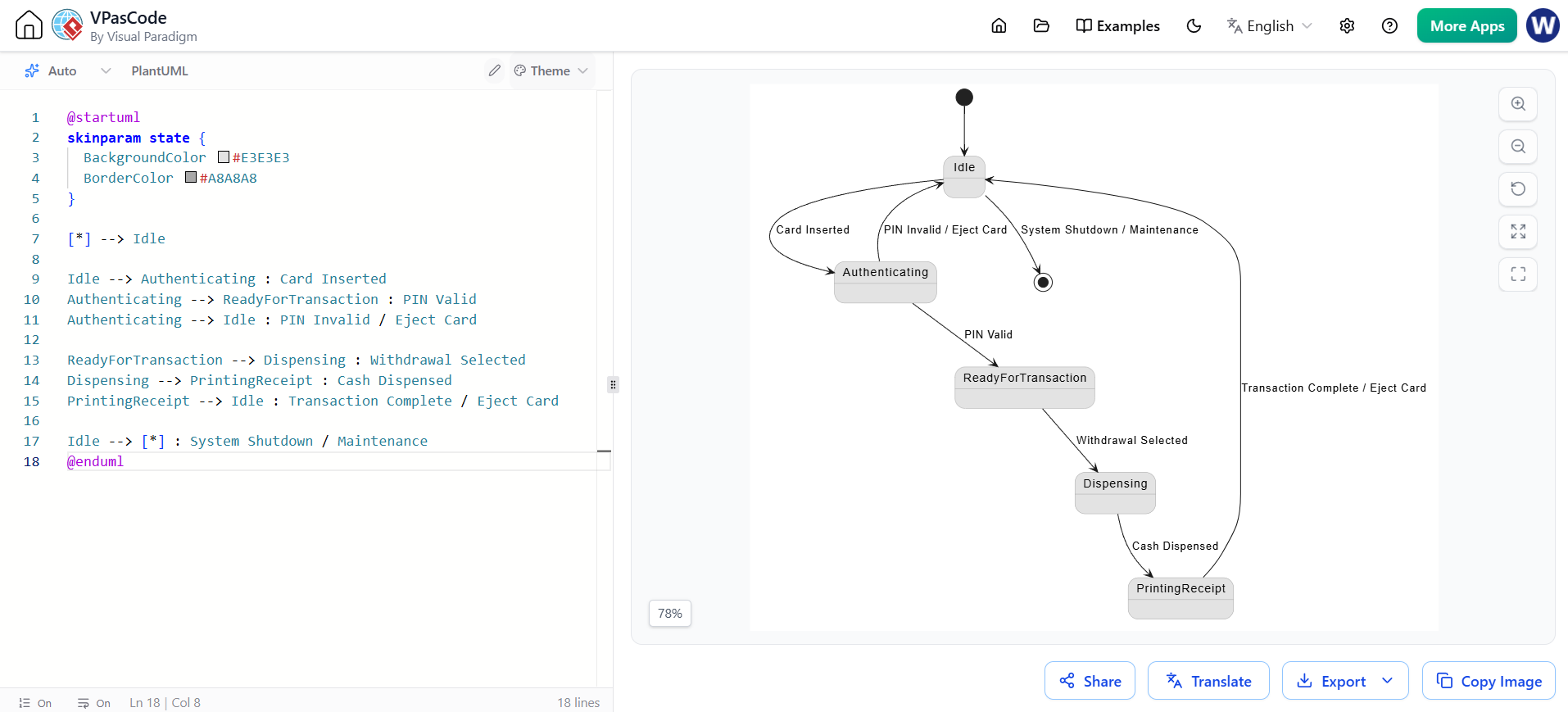
Behavioral: Uses statechart diagrams to define the dynamic life cycle and state transitions of internal objects.
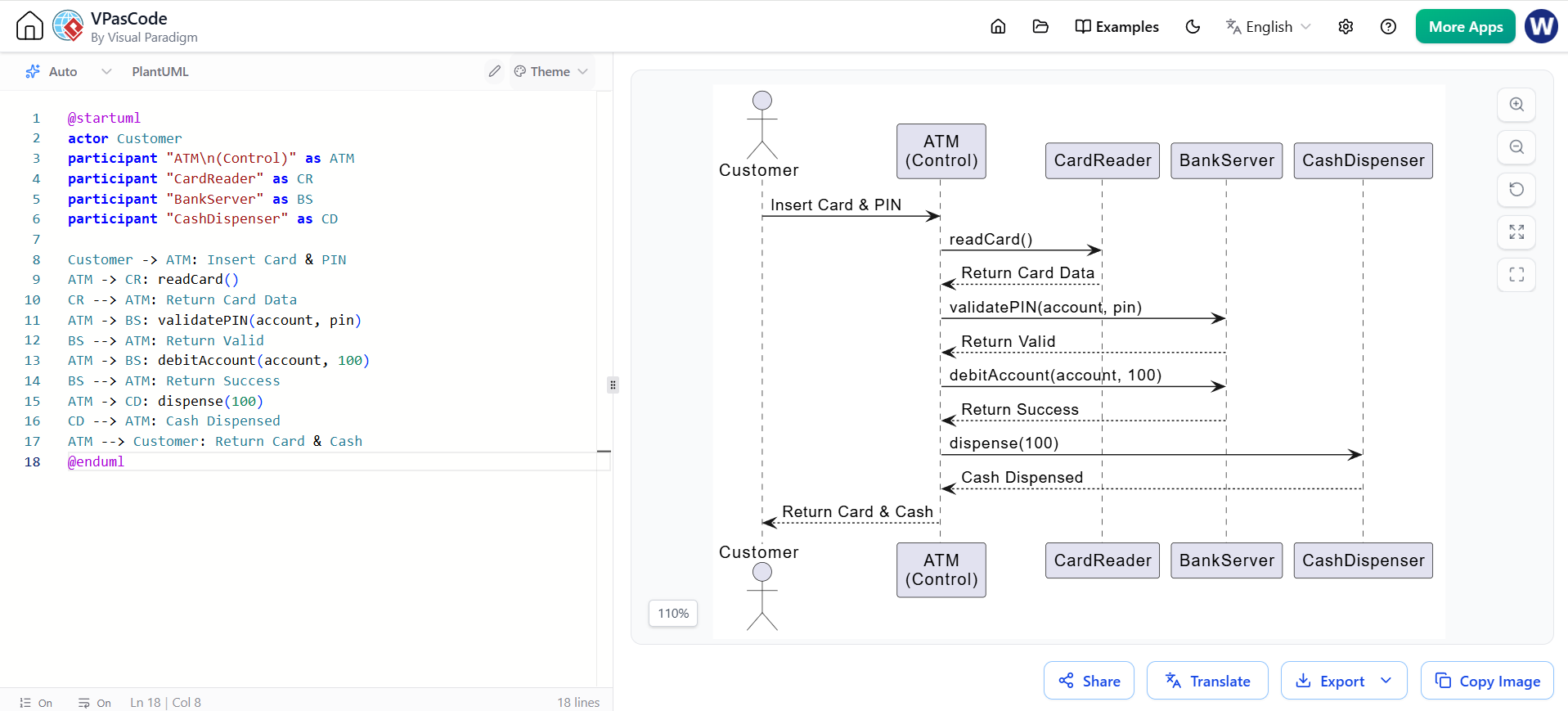
Interaction: Uses sequence and communication diagrams to show how internal objects delegate work and send messages/events to each other to fulfill a user's request.
To maintain their respective perspectives, the external and internal views prioritize different types of UML diagrams:
Use Case Diagrams: Provide a functional overview of the system's capabilities from the user's perspective.
High-Level Activity Diagrams: Map out the overarching process flow and user journeys.
Use Case Sequence Diagrams: Illustrate the chronological exchange of query and mutation events between the actor and the system boundary.
Package Diagrams: Model high-level organization (business units or software modules).
Detailed Class Diagrams: Define the static structure, attributes, and relationships of internal components.
Statechart Diagrams: Model the behavioral lifecycle of complex internal objects.
Interaction Diagrams (Sequence/Communication): Detail the object-to-object messaging and delegation required to execute a use case.
To solidify these concepts, let's model an Automated Teller Machine (ATM) system. We will first look at it through the External View, and then "open the box" to look at the Internal View.
This diagram represents the "Black Box" perspective. The user only sees the services provided, not the internal mechanics.
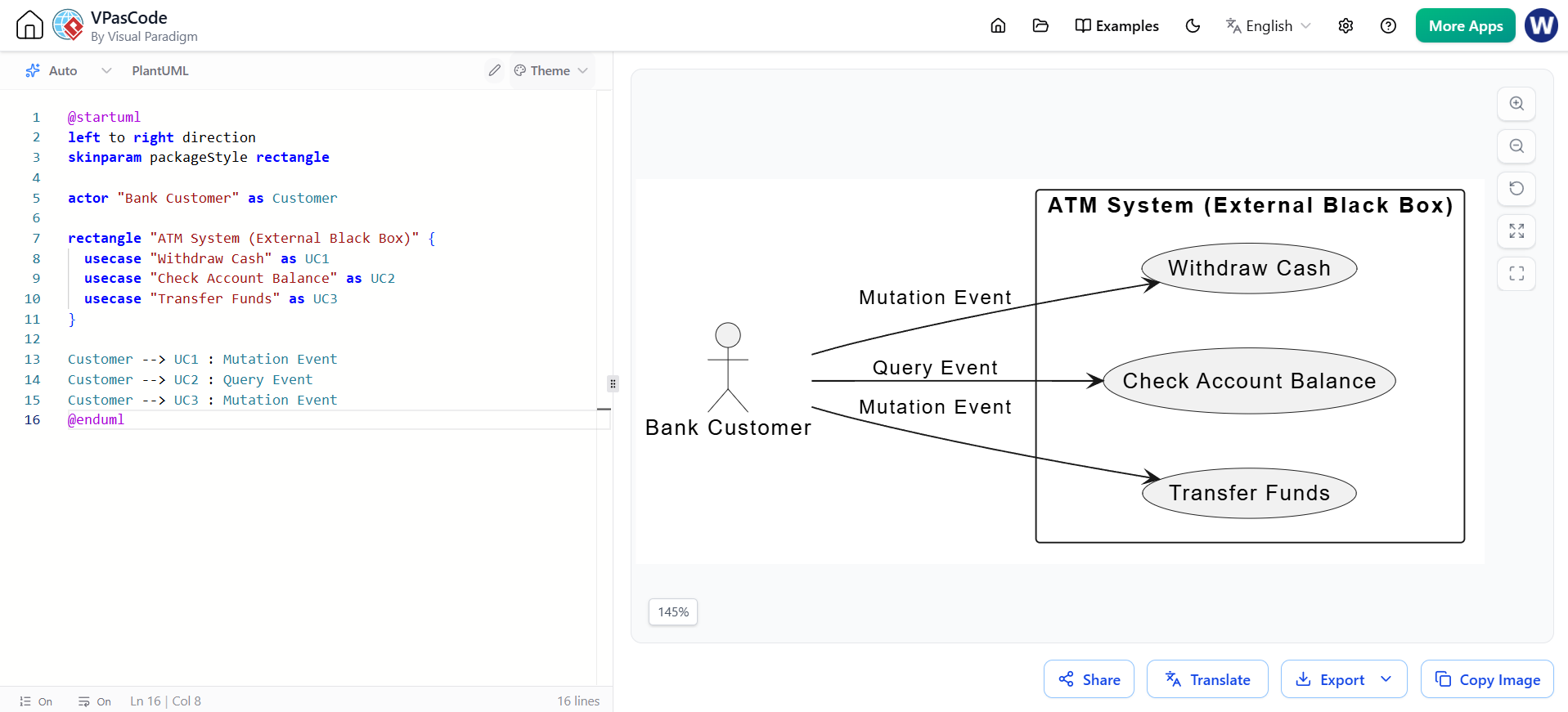
@startuml
left to right direction
skinparam packageStyle rectangle

actor "Bank Customer" as Customer

rectangle "ATM System (External Black Box)" {
  usecase "Withdraw Cash" as UC1
  usecase "Check Account Balance" as UC2
  usecase "Transfer Funds" as UC3
}

Customer --> UC1 : Mutation Event
Customer --> UC2 : Query Event
Customer --> UC3 : Mutation Event
@enduml
This shows the chronological interaction between the user and the system boundary, utilizing query and mutation events without exposing internal objects.
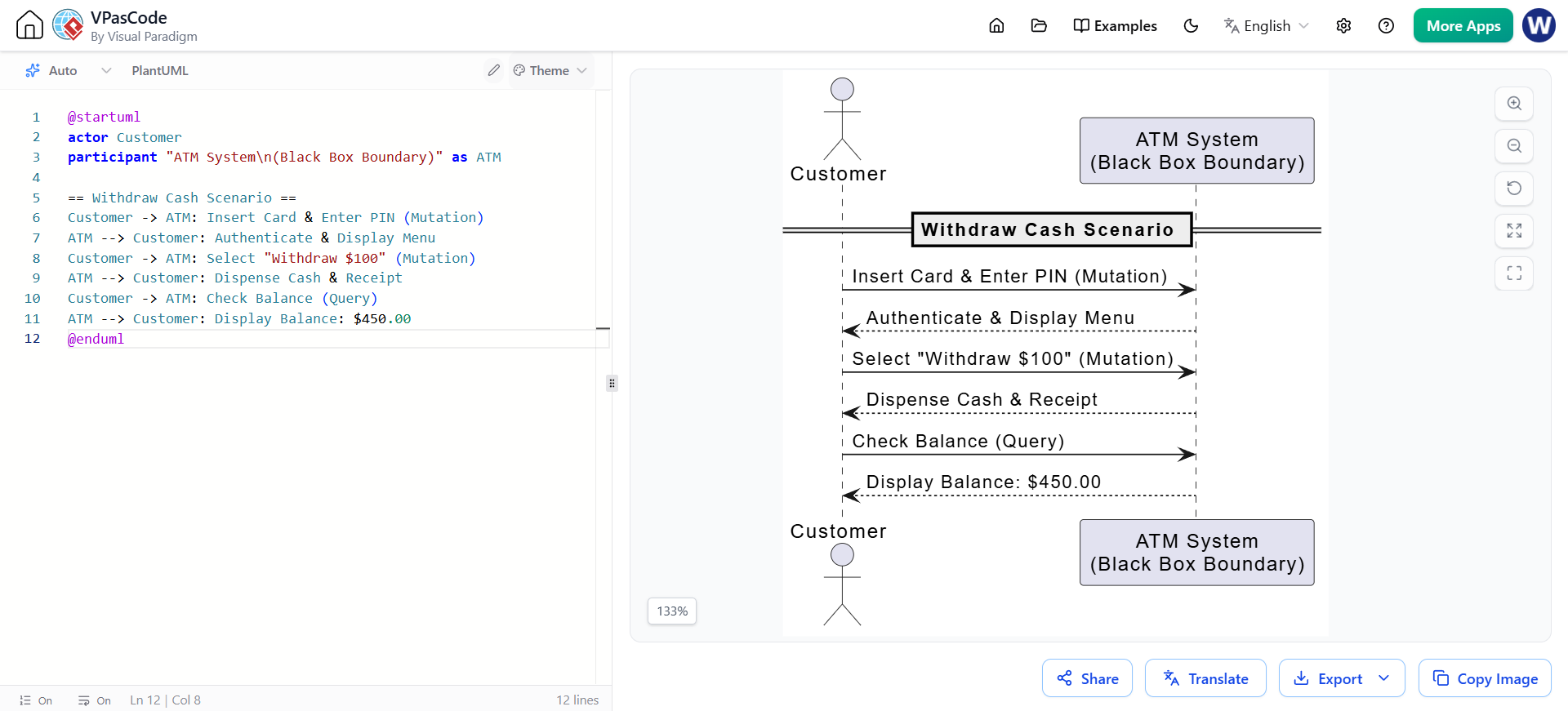
@startuml
actor Customer
participant "ATM System\n(Black Box Boundary)" as ATM

== Withdraw Cash Scenario ==
Customer -> ATM: Insert Card & Enter PIN (Mutation)
ATM --> Customer: Authenticate & Display Menu
Customer -> ATM: Select "Withdraw $100" (Mutation)
ATM --> Customer: Dispense Cash & Receipt
Customer -> ATM: Check Balance (Query)
ATM --> Customer: Display Balance: $450.00
@enduml
Now we open the white box. This diagram reveals the internal static structure, showing the specific classes (CardReader, CashDispenser, BankServer) that make up the ATM.
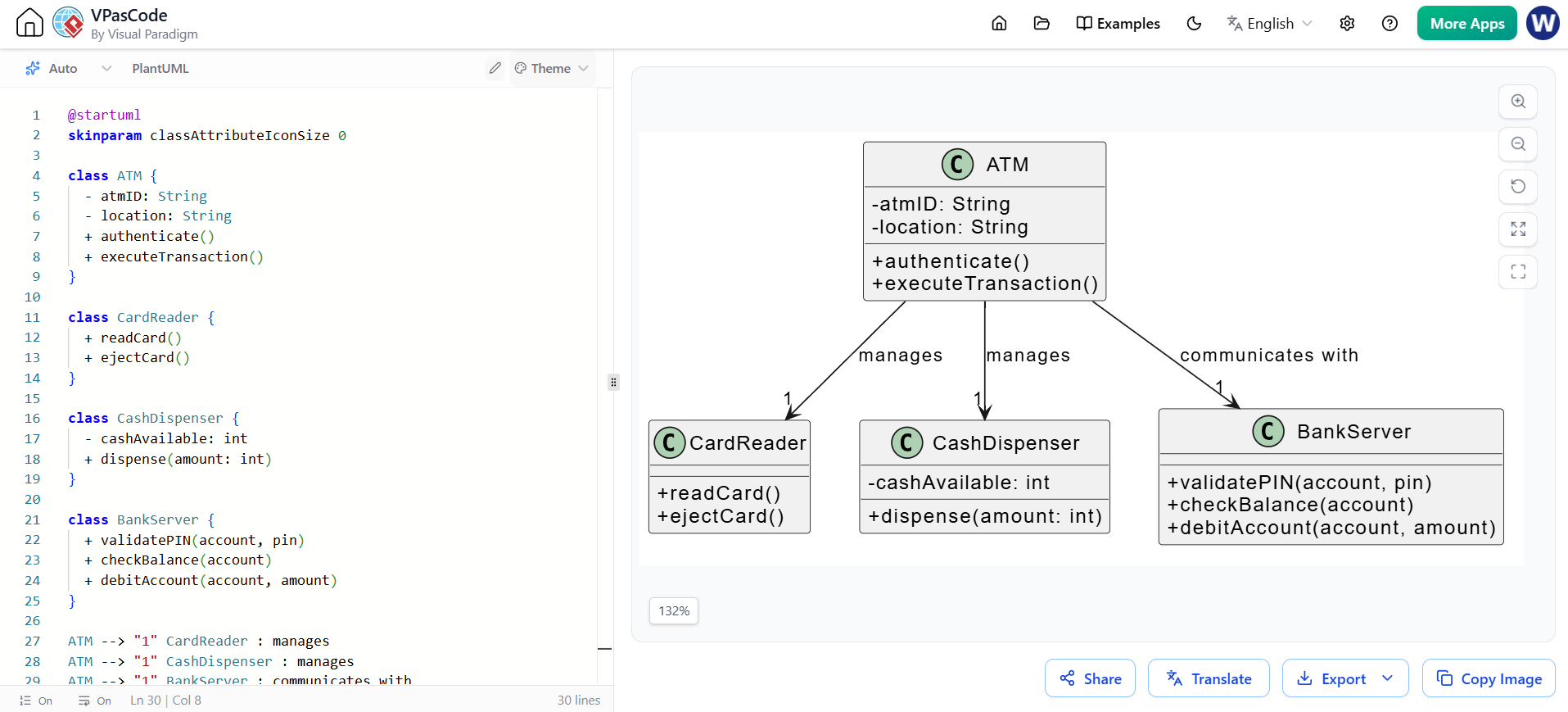
@startuml
skinparam classAttributeIconSize 0

class ATM {
  - atmID: String
  - location: String
  + authenticate()
  + executeTransaction()
}

class CardReader {
  + readCard()
  + ejectCard()
}

class CashDispenser {
  - cashAvailable: int
  + dispense(amount: int)
}

class BankServer {
  + validatePIN(account, pin)
  + checkBalance(account)
  + debitAccount(account, amount)
}

ATM --> "1" CardReader : manages
ATM --> "1" CashDispenser : manages
ATM --> "1" BankServer : communicates with
@enduml
This diagram reveals the internal collaboration. It shows how the ATM object delegates tasks to the CardReader, BankServer, and CashDispenser to fulfill the user's external request.
@startuml
actor Customer
participant "ATM\n(Control)" as ATM
participant "CardReader" as CR
participant "BankServer" as BS
participant "CashDispenser" as CD

Customer -> ATM: Insert Card & PIN
ATM -> CR: readCard()
CR --> ATM: Return Card Data
ATM -> BS: validatePIN(account, pin)
BS --> ATM: Return Valid
ATM -> BS: debitAccount(account, 100)
BS --> ATM: Return Success
ATM -> CD: dispense(100)
CD --> ATM: Cash Dispensed
ATM --> Customer: Return Card & Cash
@enduml
This diagram models the dynamic lifecycle of the internal ATM object, showing how it transitions between different internal states based on events.
@startuml
skinparam state {
  BackgroundColor #E3E3E3
  BorderColor #A8A8A8
}

[*] --> Idle

Idle --> Authenticating : Card Inserted
Authenticating --> ReadyForTransaction : PIN Valid
Authenticating --> Idle : PIN Invalid / Eject Card

ReadyForTransaction --> Dispensing : Withdrawal Selected
Dispensing --> PrintingReceipt : Cash Dispensed
PrintingReceipt --> Idle : Transaction Complete / Eject Card

Idle --> [*] : System Shutdown / Maintenance
@enduml
Mastering the distinction between UML’s external and internal views is fundamental to successful system architecture and business analysis.
The External View ensures that you are building the right thing. By treating the system as a black box, you maintain a laser focus on user needs, observable business value, and functional requirements without getting bogged down by technical complexities. It is the bridge between stakeholders and the development team.
The Internal View ensures that you are building the thing right. By opening the white box, you define the robust structural, behavioral, and interaction mechanics required to deliver on the promises made in the external view. It is the blueprint for the engineering team.
By utilizing the appropriate UML diagrams for each perspective—use cases and high-level activities for the outside, and detailed classes, statecharts, and interaction diagrams for the inside—architects can create comprehensive, unambiguous models that guide a system from initial concept to flawless implementation.

