
In the architecture of any robust software application, the database serves as the foundational bedrock. However, before a single line of SQL is written or a table is indexed, successful data design begins with clarity of thought. The Entity-Relationship (ER) Model is the industry-standard conceptual framework that bridges the gap between abstract business requirements and concrete technical implementation. By visually mapping out entities, their attributes, and the complex web of relationships between them, ER Diagrams (ERDs) allow architects, developers, and stakeholders to align on a shared understanding of the data landscape.
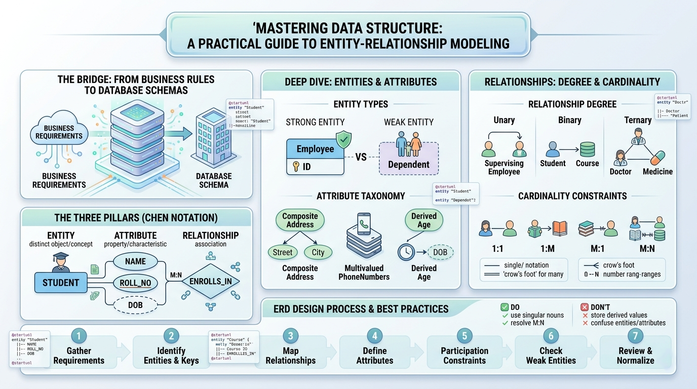
The Entity-Relationship (ER) model is the industry-standard conceptual framework for database design. It bridges the gap between real-world requirements and technical database schemas by focusing on what data needs to be stored rather than how it is physically stored.
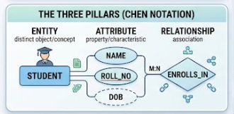
| Component | Definition | Symbol (Chen Notation) | Real-World Example |
|---|---|---|---|
| Entity | A distinct object, concept, or thing about which data is stored. | Rectangle | Student, Order, Vehicle |
| Attribute | A property or characteristic that describes an entity. | Oval | Name, Price, VIN |
| Relationship | An association or interaction between two or more entities. | Diamond | Enrolls_In, Purchases, Belongs_To |
⚠️ Critical Distinction: An ER Diagram models the schema (structure/types), not the data (instances/rows). You draw "Student," not "John Doe."
Strong Entity: Has its own primary key and exists independently.
Example: Employee (identified by EmpID).
Weak Entity: Cannot be uniquely identified without a Strong Entity. Always has total participation in an identifying relationship.
Example: Dependent (identified only via Employee + DependentName).
Understanding attribute types prevents normalization issues later:
Key Attribute: Uniquely identifies an entity instance. (Underlined Oval)
Composite Attribute: Can be broken down into sub-parts. (Oval connected to smaller ovals)
Ex: Address → {Street, City, State, Zip}
Multivalued Attribute: Can hold multiple values for a single entity. (Double Oval)
Ex: PhoneNumbers, Skills
Derived Attribute: Computed from other attributes; not stored directly. (Dashed Oval)
Ex: Age (derived from DateOfBirth)
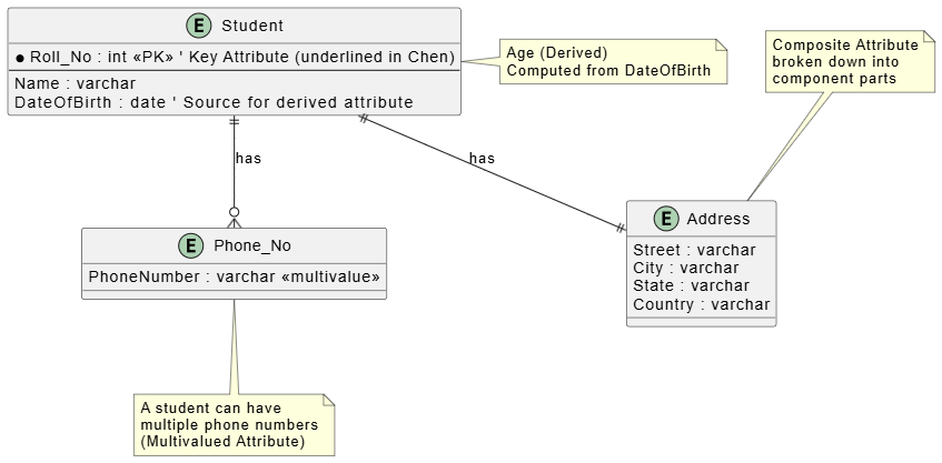
@startuml
' Entity with all attribute types shown in the article

entity "Student" as Student {
* Roll_No : int <<PK>> ' Key Attribute (underlined in Chen)
--
Name : varchar
DateOfBirth : date ' Source for derived attribute
}

' Derived Attribute - Age (computed from DateOfBirth)
note right of Student : Age (Derived)\nComputed from DateOfBirth

' Multivalued Attribute - Phone Numbers
entity "Phone_No" as Phone {
PhoneNumber : varchar <<multivalue>>
}

' Composite Attribute - Address
entity "Address" as Address {
Street : varchar
City : varchar
State : varchar
Country : varchar
}

' Relationships showing attribute structure
Student ||--o{ Phone : "has"
Student ||--|| Address : "has"

note bottom of Phone
A student can have
multiple phone numbers
(Multivalued Attribute)
end note

note top of Address
Composite Attribute
broken down into
component parts
end note

@enduml
Unary (Recursive): One entity set relates to itself. Ex: Employee supervises Employee.
Binary: Two entity sets. Ex: Student enrolls in Course. (Most common)
Ternary/N-ary: Three or more entity sets. Ex: Doctor prescribes Medicine to Patient.
Cardinality defines the maximum number of times an entity participates in a relationship.
| Type | Notation | Meaning | Example |
|---|---|---|---|
| One-to-One (1:1) | 1 ──── 1 |
Each entity maps to at most one other entity. | Person ↔ Passport |
| One-to-Many (1:M) | 1 ──── M |
One entity maps to many; each "many" maps to one. | Department → Doctors |
| Many-to-One (M:1) | M ──── 1 |
Inverse of 1:M. | Surgeries ← Surgeon |
| Many-to-Many (M:N) | M ──── N |
Both sides can map to multiple entities. | Students ↔ Courses |
Total Participation (Mandatory): Every entity MUST participate. Represented by a double line.
Ex: Every Dependent MUST belong to an Employee.
Partial Participation (Optional): Entities MAY participate. Represented by a single line.
Ex: Some Courses may have zero enrolled students.
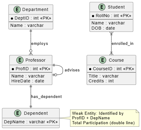
@startuml
entity "Department" as dept {
  * DeptID : int <<PK>>
  --
  Name : varchar
}

entity "Professor" as prof {
  * ProfID : int <<PK>>
  --
  Name : varchar
  HireDate : date
}

entity "Course" as course {
  * CourseID : int <<PK>>
  --
  Title : varchar
  Credits : int
}

entity "Student" as student {
  * RollNo : int <<PK>>
  --
  Name : varchar
  DOB : date
}

' === Relationships ===

' 1:M - Department has many Professors (Total participation for Prof)
dept ||--o{ prof : "employs"

' M:N - Students enroll in Courses
student }|--|{ course : "enrolled_in"

' Unary - Professor advises Professor
prof ||--o| prof : "advises"

' Weak Entity Example
entity "Dependent" as dep {
  DepName : varchar <<PK>>
}
prof ||--|| dep : "has_dependent"

note right of dep
  Weak Entity: Identified by
  ProfID + DepName
  Total Participation (double line)
end note
@enduml
Follow this systematic approach to avoid costly redesigns:
Gather Requirements: Interview stakeholders. Identify nouns (entities) and verbs (relationships).
Identify Entities & Keys: List all entity types and their primary keys first.
Map Relationships: Connect entities. Determine degree (binary/ternary) and cardinality (1:1, 1:M, M:N).
Define Attributes: Add descriptive properties. Classify them (composite, multivalued, derived).
Apply Participation Constraints: Ask "Is this mandatory or optional?" for each side of every relationship.
Check for Weak Entities: Identify any entity that lacks an independent primary key.
Review & Normalize: Eliminate redundancies. Ensure no M:N relationships remain unaddressed if moving toward relational implementation.
Use Singular Nouns: Entity names should be singular (Student, not Students). Tables represent sets, but the entity type is a single concept.
Resolve M:N Early: In logical design, M:N is fine. In physical design, always decompose M:N into two 1:M relationships via an associative/junction entity (e.g., Enrollment table linking Student and Course).
Name Relationships as Verbs: Use active voice (Places, Teaches, Manages) instead of vague labels like Has or Related_To.
Validate with Sample Data: Mentally insert 3-5 sample records. Does your cardinality hold? Does total participation make sense with edge cases?
Document Assumptions: ER diagrams cannot capture business rules alone. Maintain a companion data dictionary.
Don't Store Derived Values: Never store Age if you have DOB. Store the source; compute the derivative.
Don't Confuse Entities with Attributes: If something has its own attributes and relationships, it's likely an entity, not an attribute. Test: Can "Skill" have a category, proficiency level, and certification date? Then it's an entity, not a multivalued attribute of Employee.
Don't Over-Normalize Prematurely: Conceptual modeling prioritizes clarity over 3NF. Optimize during physical design.
Don't Ignore Weak Entities: Treating a weak entity as strong leads to orphaned records and integrity violations.
Don't Draw Direct Entity-to-Entity Lines Without Labels: Every connection must pass through a named relationship diamond (in Chen notation) or have a labeled connector (in Crow's Foot/UML).
Use Stereotypes: <<PK>>, <<FK>>, <<weak>>, <<derived>> improve readability.
Layer Your Diagrams: Create separate diagrams for overview vs. detailed attribute views. Large ERDs become unreadable quickly.
Consistent Naming Convention: Choose snake_case, camelCase, or PascalCase and stick to it across all entities and attributes.
Version Control Your .puml Files: Treat ER diagrams as code. Store them in Git alongside your SQL migrations.
| Concept | Chen Symbol | PlantUML / UML Equivalent | Key Question to Ask |
|---|---|---|---|
| Strong Entity | Rectangle | entity X {} |
Does it have its own PK? |
| Weak Entity | Double Rectangle | entity X <<weak>> {} |
Can it exist without parent? |
| Key Attribute | Underlined Oval | * field <<PK>> |
What uniquely identifies this? |
| Multivalued Attr | Double Oval | field[] or <<multivalue>> |
Can this have >1 value per entity? |
| Derived Attr | Dashed Oval | <<derived>> field |
Can this be calculated? |
| Total Participation | Double Line | ||-- or ||-\{ |
Is this relationship mandatory? |
| M:N Relationship | Diamond + M,N lines | }--|{ |
Do both sides allow multiples? |
Designing a database is less about memorizing syntax and more about accurately modeling real-world logic. By mastering the Entity-Relationship model, you gain the ability to translate complex business rules into a structured, visual format that prevents costly redesigns down the road. Whether you are distinguishing between strong and weak entities, resolving many-to-many relationships, or defining strict participation constraints, the principles outlined in this guide serve as your blueprint for data integrity. Remember that an ERD is a living document; as your application evolves, so too should your model. Use the PlantUML snippets and best practices provided here not just as a reference, but as a starting point for iterative, collaborative design. With a clear conceptual model in hand, you are well-equipped to move confidently from logical design to physical implementation, ensuring your database is as resilient and efficient as the applications it supports.
This guide provides both the theoretical foundation and the practical tooling needed to design robust, well-documented database schemas using ER modeling.

