
In software engineering, effective communication and structured planning are just as critical as the code itself. The Unified Modeling Language (UML) class diagram is one of the most fundamental and widely used tools for visualizing the static structure of a software system. However, a common misconception among novice developers is that a class diagram is a single, static artifact created all at once.
In professional software development, class diagrams are dynamic. They evolve in tandem with the project lifecycle, undergoing a process of progressive elaboration. This evolution is typically classified into three distinct stages: Domain-Level, Analysis-Level, and Design-Level.
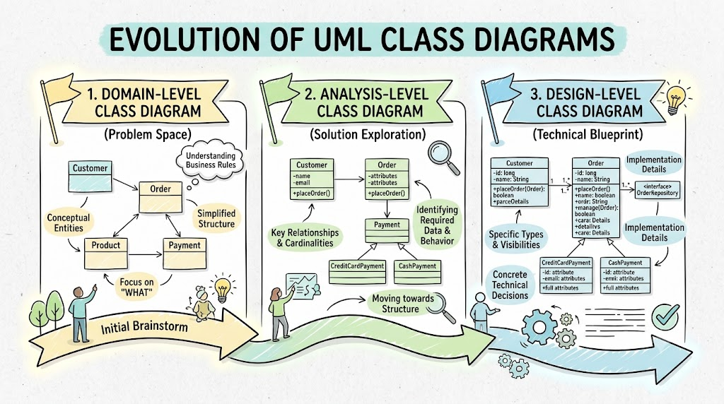
This guide explores these three stages in detail, providing the key concepts, structural characteristics, and practical PlantUML examples to help you master the art of evolving your UML models from abstract business concepts to concrete technical blueprints.
Before diving into the specific stages, it is essential to understand the underlying principles that drive the evolution of UML class diagrams:
Progressive Elaboration: Software models should start broad and abstract, gradually becoming more detailed and specific. This prevents "analysis paralysis" and avoids premature technical lock-in before business requirements are fully understood.
Separation of Concerns: Each stage focuses on a different layer of the system. The domain focuses on what the business is; the analysis focuses on the structural rules of the business; and the design focuses on how the system will be technically built.
Ubiquitous Language: Early-stage diagrams help bridge the gap between technical and non-technical stakeholders by establishing a shared vocabulary.
Model-Driven Architecture (MDA) Alignment: The transition from abstract to concrete mirrors the MDA concept of transforming a Platform-Independent Model (PIM) into a Platform-Specific Model (PSM).
The Domain-Level class diagram is created during the initial requirements gathering phase. Its primary goal is not to define software architecture, but to establish the initial core vocabulary of the system.
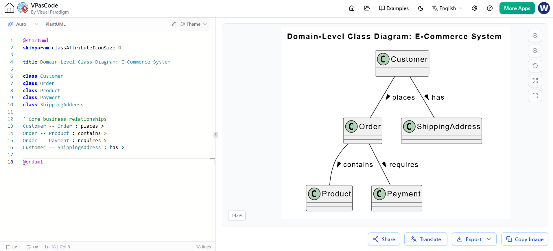
Content: Shows only the names of the classes and the high-level relationships (associations) between them. No attributes or methods are included.
Purpose: To facilitate a common understanding of business terms among stakeholders, product owners, and developers. It ensures everyone is talking about the same concepts.
Abstraction Level: Highly abstract. These diagrams are directly comparable to Platform-Independent Models (PIMs) in Model-Driven Architecture, as they contain zero technical or implementation details.
Notice how clean and simple the diagram is. It only defines the core entities and how they relate.
@startuml
skinparam classAttributeIconSize 0

title Domain-Level Class Diagram: E-Commerce System

class Customer
class Order
class Product
class Payment
class ShippingAddress

' Core business relationships
Customer -- Order : places >
Order -- Product : contains >
Order -- Payment : requires >
Customer -- ShippingAddress : has >

@enduml
As the development team gains a deeper understanding of the domain, the diagram evolves into the Analysis-Level. This stage captures the structural rules and data requirements of the system without getting bogged down in technical implementation.
Content: Expands on the domain model by adding attributes, multiplicity (e.g., 1..*), and role names for associations.
Exclusions: They generally do not include operations (methods). Deciding the specific behavior and internal logic for each class is considered a design-level activity.
Constraints: High-level business or design constraints may be included. For example, adding a {encrypted} constraint to a password attribute indicates a security requirement without dictating the specific encryption algorithm.
Here, we add attributes, data types, multiplicities, and a high-level constraint ({encrypted}), but we still avoid defining methods.

@startuml
skinparam classAttributeIconSize 0

title Analysis-Level Class Diagram: E-Commerce System

class Customer {
  + customerId: String
  + email: String
  + password: String {encrypted}
  + registrationDate: Date
}

class Order {
  + orderId: String
  + orderDate: Date
  + status: String
  + totalAmount: Decimal
}

class OrderItem {
  + quantity: Integer
  + unitPrice: Decimal
}

class Product {
  + productId: String
  + name: String
  + basePrice: Decimal
  + stockCount: Integer
}

class Payment {
  + transactionId: String
  + amount: Decimal
  + paymentMethod: String
}

' Relationships with multiplicities and role names
Customer "1" -- "0..*" Order : places >
Order "1" -- "1..*" OrderItem : includes >
OrderItem "0..*" -- "1" Product : refers to >
Order "1" -- "0..1" Payment : settles via >

@enduml
The Design-Level class diagram is the most detailed version, serving as the direct blueprint for developers. It translates the structural analysis into a concrete technical implementation plan.
Content: Expands on the analysis model by adding operations (methods), complete with visibility (public/private), parameters, and return types.
Technical Detail: These diagrams map abstract concepts to specific technology stacks and architectural patterns. They can illustrate:
Mapping classes to UI components like HTML pages or JavaServer Pages (JSP).
Specifying backend architectures, such as Enterprise JavaBeans (EJB) types (e.g., <<entity>>, <<session>>).
Illustrating complex design patterns, such as the separation of remote interfaces from their concrete implementation classes.
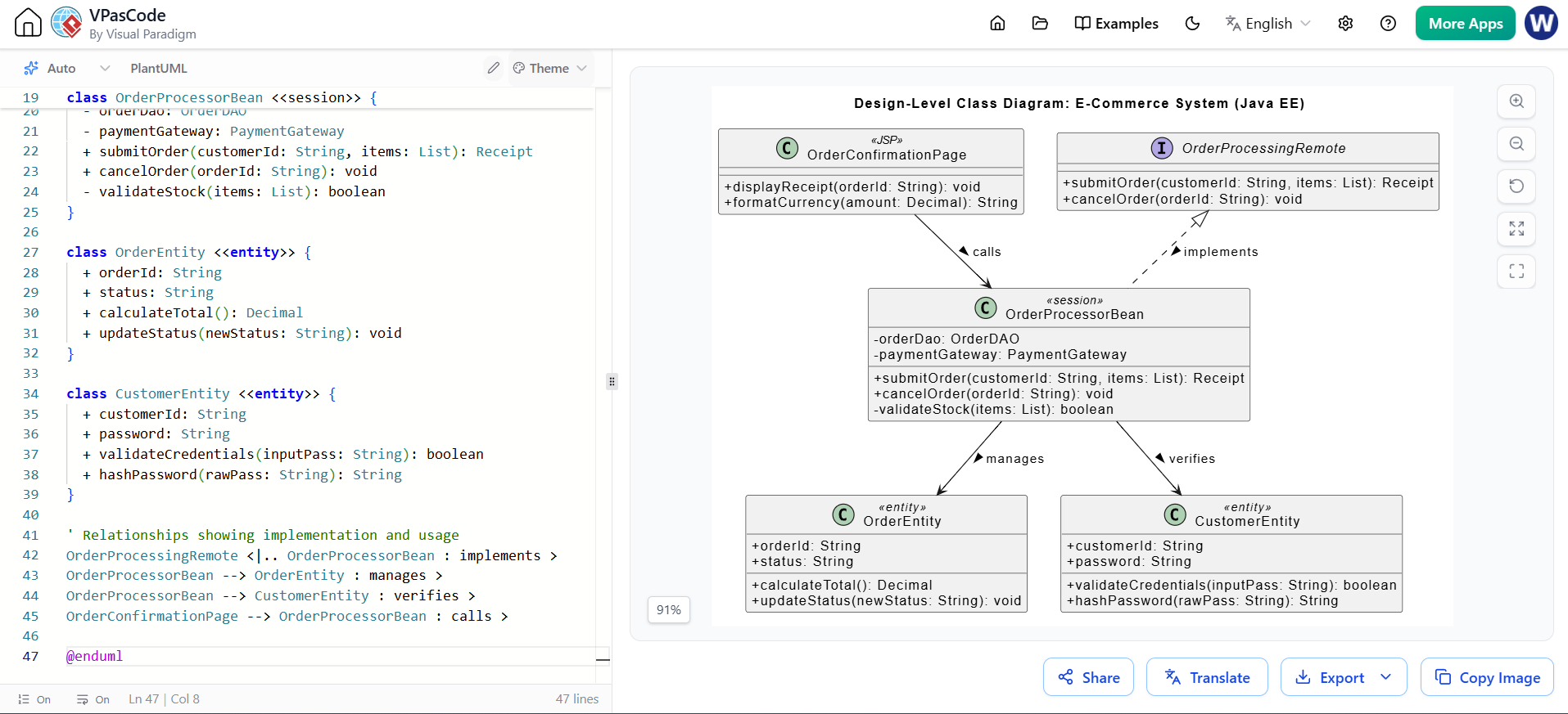
This diagram introduces operations, stereotypes for specific technologies (JSP, EJB), and separates interfaces from implementations to show architectural patterns.
@startuml
skinparam classAttributeIconSize 0

title Design-Level Class Diagram: E-Commerce System (Java EE)

' UI Layer
class OrderConfirmationPage <<JSP>> {
  + displayReceipt(orderId: String): void
  + formatCurrency(amount: Decimal): String
}

' Interface Layer
interface OrderProcessingRemote {
  + submitOrder(customerId: String, items: List): Receipt
  + cancelOrder(orderId: String): void
}

' EJB Implementation Layer
class OrderProcessorBean <<session>> {
  - orderDao: OrderDAO
  - paymentGateway: PaymentGateway
  + submitOrder(customerId: String, items: List): Receipt
  + cancelOrder(orderId: String): void
  - validateStock(items: List): boolean
}

class OrderEntity <<entity>> {
  + orderId: String
  + status: String
  + calculateTotal(): Decimal
  + updateStatus(newStatus: String): void
}

class CustomerEntity <<entity>> {
  + customerId: String
  + password: String
  + validateCredentials(inputPass: String): boolean
  + hashPassword(rawPass: String): String
}

' Relationships showing implementation and usage
OrderProcessingRemote <|.. OrderProcessorBean : implements >
OrderProcessorBean --> OrderEntity : manages >
OrderProcessorBean --> CustomerEntity : verifies >
OrderConfirmationPage --> OrderProcessorBean : calls >

@enduml
The progression from Domain-Level to Analysis-Level, and finally to Design-Level class diagrams, represents a mature approach to software modeling. By respecting these three stages, development teams can ensure that they fully understand the business problem before attempting to solve it with code.
Domain-Level ensures everyone speaks the same language.
Analysis-Level defines the structural rules and data requirements without premature technical bias.
Design-Level provides the exact technical blueprint required for implementation.
Adopting this evolutionary mindset prevents costly rework, improves communication between business stakeholders and developers, and results in a cleaner, more maintainable software architecture. Whether you are building a simple web application or a complex enterprise system, letting your UML diagrams evolve through these three stages is a best practice that will pay dividends throughout your project's lifecycle.

