Welcome to this tutorial on Visual Paradigm’s SysML v2 Studio.
One of the most powerful features of SysML v2 is its textual nature. Unlike older modeling tools where you draw a box and the tool generates code in the background, SysML v2 is “Text-First.”
However, diagrams are still incredibly useful for visualization. This tutorial explains the Context-Aware Rendering feature. This means the Diagram View on the right is dynamic—it changes automatically based on where your cursor is located in the code editor on the left.
The diagram renders the Scope relevant to the line of code indicated by the red arrow.
Context: Defining the “Shape” of a connection.
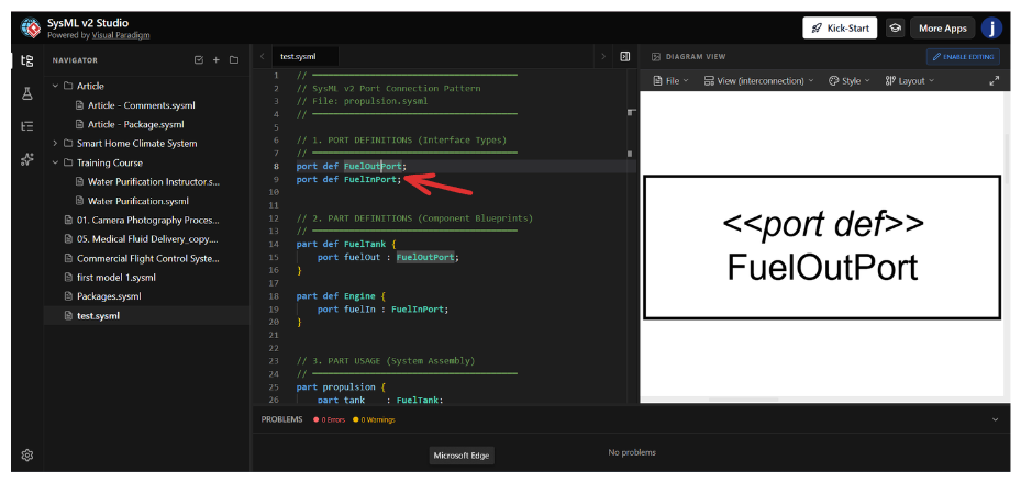
Look at: Screenshot 1
Cursor Location (Red Arrow): Line 8, port def FuelOutPort.
What happens:
When you place your cursor on a Port Definition (a type of interface), the diagram renders that specific interface definition.
The Diagram:
You see a box labeled <<port def>> FuelOutPort.
Why this matters:
You are looking at the blueprint of the port. It tells you, “This is what a fuel output port looks like,” without showing you which specific tank or engine is using it yet.
Context: Viewing the overall structure.
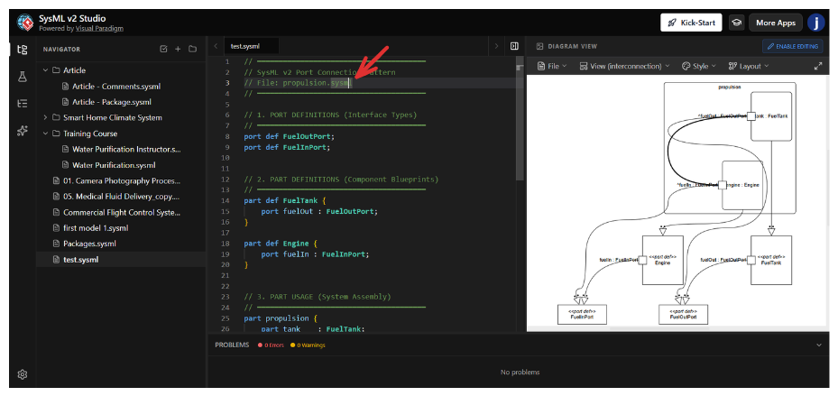
Look at: Screenshot 2
Cursor Location (Red Arrow): Line 1, The file header/comment // SysML v2 Port Connection Pattern.
What happens:
When your cursor is at the very top of the file (outside of any specific block), the tool renders the Top-Level Scope. It shows you the aggregate view of everything contained within that file.
The Diagram:
You see a hierarchy. You can see the propulsion system, containing the tank and engine, and how they are linked.
Why this matters:
This is your “Zoomed Out” view. It is perfect for understanding how all the pieces of your text file fit together as a complete system.
Context: Defining a reusable component.
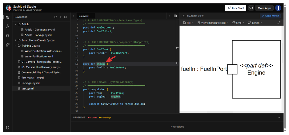
Look at: Screenshot 3
Cursor Location (Red Arrow): Line 18, part def Engine.
What happens:
Here, the cursor is inside a Part Definition. You are defining the type of object called “Engine,” not a specific physical engine.
The Diagram:
The diagram shows <<part def>> Engine. Inside, it shows the ports that every engine of this type must have (in this case, fuelIn).
Why this matters:
You are verifying the design of the component class. If you are building a library of parts, you use this view to ensure your “Engine” blueprint has the correct ports defined before you use it in a system.
Context: Assembling specific parts into a system.
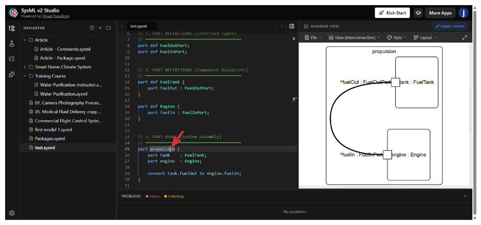
Look at: Screenshot 4
Cursor Location (Red Arrow): Line 25, part propulsion.
What happens:
The cursor is now on a Part Usage (an instantiation). The code part propulsion { ... } is creating a specific instance of a system.
The Diagram:
The diagram changes to show the Instance View. It shows the propulsion block containing specific parts: tank : FuelTank and engine : Engine. It visualizes how these specific instances are assembled.
Why this matters:
This is distinct from the Definition view. Here, you are looking at a specific assembly. You can see that inside this specific propulsion system, there is a tank and an engine working together.
Context: Defining how data or matter flows.
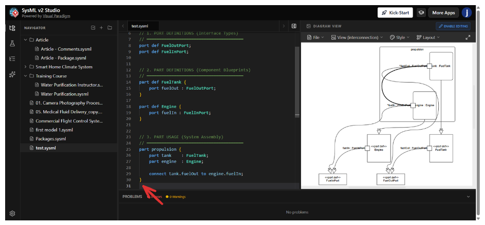
Look at: Screenshot 5
Cursor Location (Red Arrow): Line 29, connect tank.fuelout to engine.fuelIn.
What happens:
The cursor is on a connection statement. This statement lives inside the propulsion block.
The Diagram:
The diagram highlights the connectivity. You see the line connecting the fuelOut port of the tank to the fuelIn port of the engine.
Why this matters:
This provides immediate visual feedback on your logic. If you typed the connection wrong in the text, the diagram would either show a broken line or fail to render the connection, helping you debug your system architecture instantly.
| Cursor Location (Scope) | Diagram View Rendered | Concept |
|---|---|---|
port def ... |
Single Port Box | Interface Definition: Defining a port type. |
| File Header / Top Level | Full Hierarchy | Package View: How all parts relate in the file. |
part def ... |
Component with Ports | Component Blueprint: Defining a reusable part type. |
part usage { ... } |
Assembled System | System Assembly: Instantiating and connecting parts. |
connect ... |
Connection Lines | Flow/Connectivity: Visualizing the links between parts. |
Key Takeaway: In SysML v2 Studio, you don’t need to switch between different diagram windows. Simply click on the code you are interested in, and the Diagram View will automatically render the relevant visualization for that scope.