The Unified Modeling Language (UML) was developed in the 1990s to provide a consistent way to visualize, specify, construct, and document software systems. It includes structural diagrams (e.g., class, component, deployment) and behavioral diagrams (e.g., use case, sequence, activity).
In the era of Agile, DevOps, and microservices, UML has sometimes been criticized as heavyweight or outdated—associated with Big Design Up Front (BDUF) and lengthy documentation that slows iteration. However, when used pragmatically as a communication and reasoning tool rather than exhaustive upfront artifacts, UML enhances clarity, reduces risks, and supports rapid delivery in complex environments.
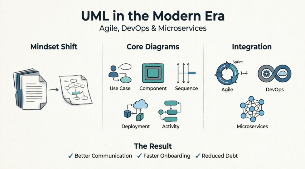
Modern teams deal with distributed systems, frequent deployments, cross-functional collaboration, and operational concerns. Lightweight, targeted UML diagrams help bridge gaps between product owners, developers, architects, and operations without becoming bureaucratic overhead. The key is "just enough" modeling: iterative, version-controlled, tied to code and decisions, and discarded when no longer useful.
This guide covers key concepts, recommended practices, and examples tailored to Agile/DevOps/microservices contexts.
Treat diagrams as aids for discussion, spikes, decision-making, and onboarding—not permanent comprehensive documentation.
Follow Agile Modeling principles: Keep it simple, iterate, use the right artifact, and apply modeling standards.
Integrate with Architecture Decision Records (ADRs): Pair diagrams with textual rationale.
Store diagrams in repositories (e.g., alongside code in Git) for versioning. Update selectively during relevant changes (e.g., via pull requests for architecture-impacting work).
Automate where possible: Generate diagrams from code or IaC where tools support it; integrate reviews into CI/CD for visibility.
Focus on a small subset—most value comes from 4–5 types:
Use Case Diagrams: High-level functionality and actors. Great for refining user stories and understanding system boundaries in Agile backlogs.
Class Diagrams: Conceptual/domain models or service internals. Use lightly for key entities; avoid over-detailing implementation.
Component Diagrams: Show services, interfaces, and dependencies—ideal for microservices architectures.
Sequence Diagrams: Model interactions, flows, and failure modes (e.g., API calls, event flows via Kafka). Excellent for design spikes and incident analysis.
Deployment Diagrams: Critical for DevOps and microservices—visualize nodes, containers, clusters (e.g., Kubernetes), communication paths, and environments. Highlight infrastructure, scaling, security zones, and observability.
Activity Diagrams: Workflows, business processes, or CI/CD pipelines.
Best Practices:
Keep diagrams small and focused (one perspective per diagram).
Use stereotypes (e.g., <>, <>), colors sparingly for clarity, and notes for context.
No crossing lines; maintain readability (test by imagining printing on one page).
Version and review: Link to tasks, use in stand-ups/retrospectives/sprint planning.
For microservices: Emphasize boundaries, APIs, events, resilience (circuit breakers, retries), and deployment topology.
Iterative Refinement: Create/refine diagrams during sprints, backlog grooming, and spikes. Use for user stories and daily alignment.
Sprint Planning & Retros: Activity/sequence diagrams for workflows; review diagrams post-incident for learning.
Lightweight: Ten-minute sketches often suffice. Avoid big models that become outdated.
Tie diagrams to Infrastructure as Code (IaC): Deployment diagrams complement Terraform/Kubernetes manifests by providing human-readable overviews.
CI/CD & Observability: Reference sequence diagrams for tracing; update deployment views for environment mappings (dev/staging/prod).
"You Build It, You Run It": Diagrams help teams understand end-to-end flows, dependencies, and operational implications.
Automate updates and share in shared repos for collaboration between dev and ops.
Microservices introduce distribution, autonomy, and complexity (network latency, eventual consistency, service meshes). UML helps manage this:
Component Diagrams for service landscape and dependencies.
Deployment Diagrams for runtime topology (containers, orchestrators, regions, load balancers, message queues).
Model event-driven flows, API gateways, resilience patterns, and security (e.g., IAM boundaries).
Avoid "death star" diagrams (overly complex); use layered or contextual views.
Highlight polyglot services, databases per service, and cross-cutting concerns.
Challenges & Mitigations:
Outdated diagrams → Assign ownership and update on architectural changes.
Over-complexity → Aggregate into clusters/packages; maintain multiple focused views.
Team resistance → Demonstrate quick value in spikes or onboarding.
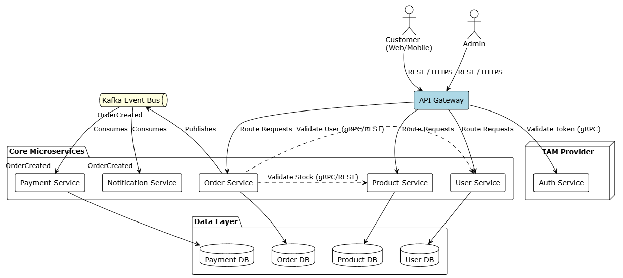
PlantUML: E-commerce Microservices Architecture
@startuml "E-commerce Microservices Architecture"

!theme plain
skinparam componentStyle rectangle
skinparam databaseStyle rectangle

' --- Actors ---
actor "Customer\n(Web/Mobile)" as customer
actor "Admin" as admin

' --- External Systems ---
node "IAM Provider" {
component "Auth Service" as auth
}

' --- API Gateway Layer ---
component "API Gateway" as gateway #LightBlue

' --- Microservices Layer ---
package "Core Microservices" {
component "User Service" as user_srv
component "Product Service" as prod_srv
component "Order Service" as order_srv
component "Payment Service" as pay_srv
component "Notification Service" as note_srv
}

' --- Event Broker Layer ---
queue "Kafka Event Bus" as kafka #LightYellow

' --- Databases (Database per Service) ---
package "Data Layer" {
database "User DB" as db_user
database "Product DB" as db_prod
database "Order DB" as db_order
database "Payment DB" as db_pay
}

' --- Relationships / Communication ---

' Actor Interactions
customer --> gateway : REST / HTTPS
admin --> gateway : REST / HTTPS

' Gateway Routing & Auth Validation
gateway --> auth : Validate Token (gRPC)
gateway --> user_srv : Route Requests
gateway --> prod_srv : Route Requests
gateway --> order_srv : Route Requests

' Internal Synchronous Communications
order_srv .r.> prod_srv : Validate Stock (gRPC/REST)
order_srv .l.> user_srv : Validate User (gRPC/REST)

' Database Per Service Constraints
user_srv --> db_user
prod_srv --> db_prod
order_srv --> db_order
pay_srv --> db_pay

' Asynchronous Event-Driven Flows
order_srv --> kafka : Publishes "OrderCreated"
kafka --> pay_srv : Consumes "OrderCreated"
kafka --> note_srv : Consumes "OrderCreated"

@endumComponent Diagram Sketch (textual representation):
Actors: Customer (via Web/Mobile), Admin.
Components: API Gateway, User Service, Product Service, Order Service, Payment Service, Notification Service.
Relationships: Synchronous REST/gRPC between services; asynchronous events via Kafka (e.g., OrderCreated → Payment & Notification).
External: Auth Service (IAM), Database per service.
This clarifies boundaries and communication styles.
User → API Gateway (with token).
Gateway → Order Service (validate).
Order Service → Payment Service (process).
Payment Service publishes "PaymentProcessed" event to Kafka.
Fraud Service consumes event → Decision.
Notification Service handles confirmation.
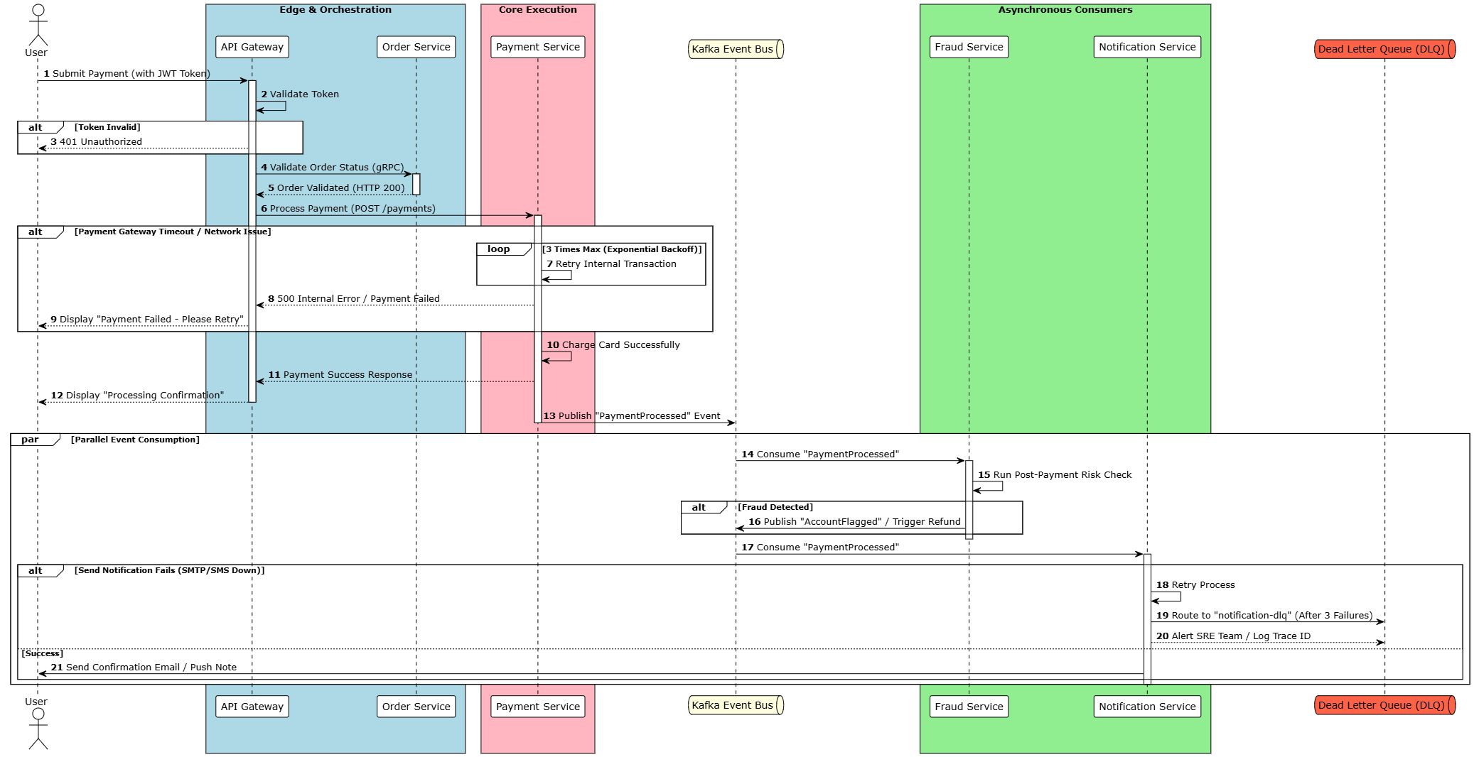
PlantUML Code:
@startuml "Payment Flow Sequence Diagram"

!theme plain
autonumber

skinparam BoxPadding 10
skinparam ParticipantPadding 10

actor "User" as user
box "Edge & Orchestration" #LightBlue
participant "API Gateway" as gateway
participant "Order Service" as order_srv
end box

box "Core Execution" #LightPink
participant "Payment Service" as pay_srv
end box

queue "Kafka Event Bus" as kafka #LightYellow

box "Asynchronous Consumers" #LightGreen
participant "Fraud Service" as fraud_srv
participant "Notification Service" as note_srv
end box

queue "Dead Letter Queue (DLQ)" as dlq #Tomato

' --- Workflow Start ---
user -> gateway : Submit Payment (with JWT Token)
activate gateway

gateway -> gateway : Validate Token
alt Token Invalid
gateway --> user : 401 Unauthorized
end

gateway -> order_srv : Validate Order Status (gRPC)
activate order_srv
order_srv --> gateway : Order Validated (HTTP 200)
deactivate order_srv

gateway -> pay_srv : Process Payment (POST /payments)
activate pay_srv

' --- Failure Point: Synchronous Payment ---
alt Payment Gateway Timeout / Network Issue
loop 3 Times Max (Exponential Backoff)
pay_srv -> pay_srv : Retry Internal Transaction
end
pay_srv --> gateway : 500 Internal Error / Payment Failed
gateway --> user : Display "Payment Failed - Please Retry"
end

pay_srv -> pay_srv : Charge Card Successfully
pay_srv --> gateway : Payment Success Response
gateway --> user : Display "Processing Confirmation"
deactivate gateway

' --- Asynchronous Event Pipeline ---
pay_srv -> kafka : Publish "PaymentProcessed" Event
deactivate pay_srv

par Parallel Event Consumption
kafka -> fraud_srv : Consume "PaymentProcessed"
activate fraud_srv
fraud_srv -> fraud_srv : Run Post-Payment Risk Check
alt Fraud Detected
fraud_srv -> kafka : Publish "AccountFlagged" / Trigger Refund
end
deactivate fraud_srv

kafka -> note_srv : Consume "PaymentProcessed"
activate note_srv

' --- Failure Point: Async Notification ---
alt Send Notification Fails (SMTP/SMS Down)
note_srv -> note_srv : Retry Process
note_srv -> dlq : Route to "notification-dlq" (After 3 Failures)
note_srv --> dlq : Alert SRE Team / Log Trace ID
else Success
note_srv -> user : Send Confirmation Email / Push Note
end
deactivate note_srv
end

@enduml
Use this in design spikes to identify failure points (e.g., retries, dead-letter queues) and align observability (tracing).
Nodes: Regional API Gateways, Kubernetes Clusters (per region), CDN, Message Brokers, External Core Systems.
Artifacts: Docker images for microservices.
Connections: , <>, WAN links.
Annotations: Scaling groups, security zones, regions for compliance.
Visual Example:
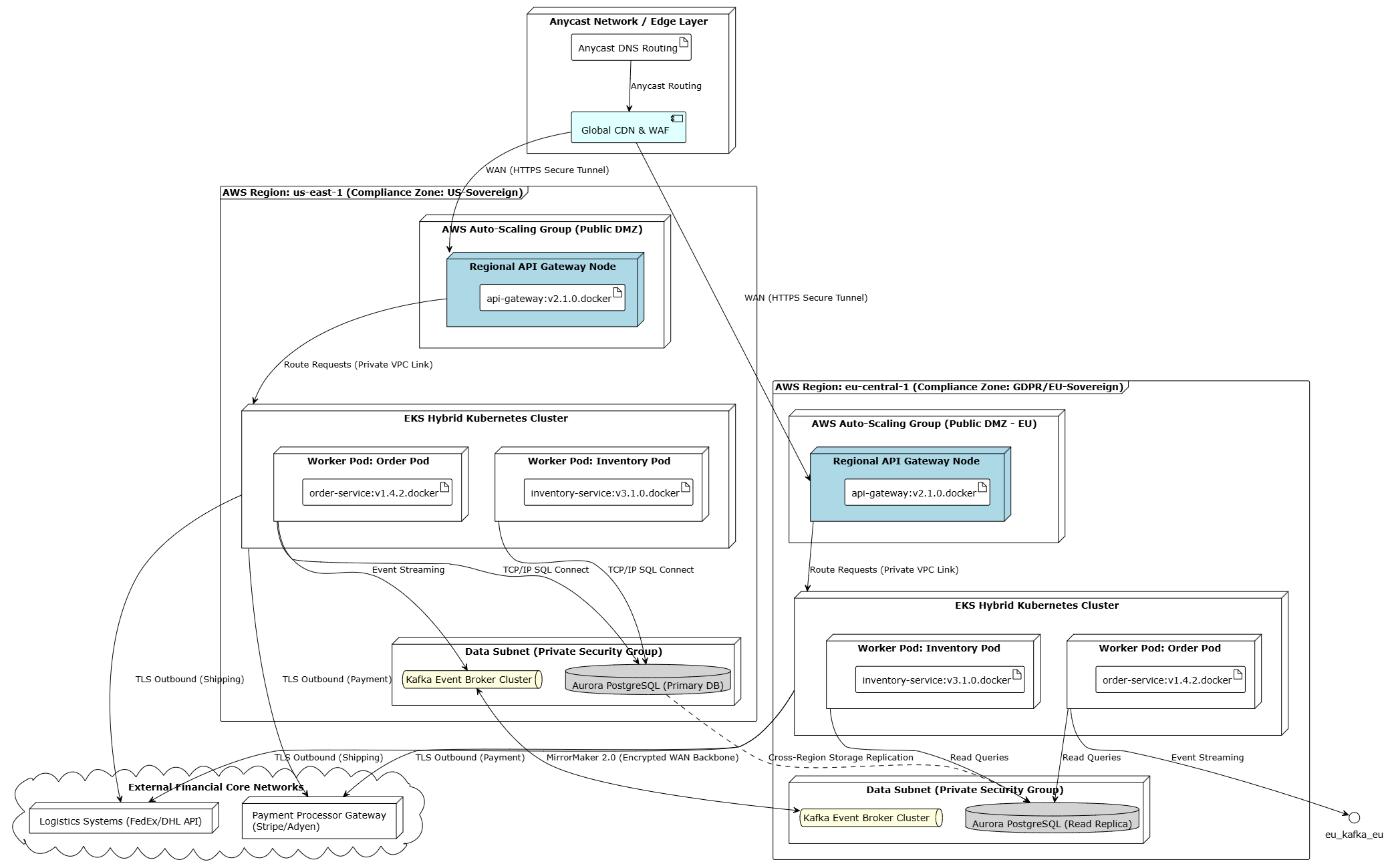
@startuml "Global E-commerce Deployment Architecture"

!theme plain
skinparam nodeStyle rectangle
skinparam frameStyle rectangle

' --- Global Networking Boundary ---
node "Anycast Network / Edge Layer" as edge_layer {
artifact "Anycast DNS Routing" as dns
component "Global CDN & WAF" as cdn #LightCyan
}

' --- REGION 1: US-EAST-1 (Primary) ---
frame "AWS Region: us-east-1 (Compliance Zone: US-Sovereign)" as us_region {

node "AWS Auto-Scaling Group (Public DMZ)" {
node "Regional API Gateway Node" as us_gw_node #LightBlue {
artifact "api-gateway:v2.1.0.docker" as us_gw_art
}
}

node "EKS Hybrid Kubernetes Cluster" as us_k8s {
node "Worker Pod: Order Pod" as us_pod_order {
artifact "order-service:v1.4.2.docker" as us_art_order
}
node "Worker Pod: Inventory Pod" as us_pod_inv {
artifact "inventory-service:v3.1.0.docker" as us_art_inv
}
}

node "Data Subnet (Private Security Group)" {
queue "Kafka Event Broker Cluster" as us_kafka #LightYellow
database "Aurora PostgreSQL (Primary DB)" as us_db #LightGray
}
}

' --- REGION 2: EU-CENTRAL-1 (Data Sovereignty Active-Active) ---
frame "AWS Region: eu-central-1 (Compliance Zone: GDPR/EU-Sovereign)" as eu_region {

node "AWS Auto-Scaling Group (Public DMZ - EU)" {
node "Regional API Gateway Node " as eu_gw_node #LightBlue {
artifact "api-gateway:v2.1.0.docker" as eu_gw_art
}
}

node "EKS Hybrid Kubernetes Cluster " as eu_k8s {
node "Worker Pod: Order Pod " as eu_pod_order {
artifact "order-service:v1.4.2.docker" as eu_art_order_eu
}
node "Worker Pod: Inventory Pod " as eu_pod_inv {
artifact "inventory-service:v3.1.0.docker" as eu_art_inv_eu
}
}

node "Data Subnet (Private Security Group) " {
queue "Kafka Event Broker Cluster " as eu_kafka #LightYellow
database "Aurora PostgreSQL (Read Replica)" as eu_db #LightGray
}
}

' --- External Systems Tier ---
cloud "External Financial Core Networks" as ext_systems {
node "Payment Processor Gateway (Stripe/Adyen)" as ext_pay
node "Logistics Systems (FedEx/DHL API)" as ext_ship
}

' --- Infrastructure Connections & Relationships ---

' Edge Entry Points
dns --> cdn : Anycast Routing
cdn --> us_gw_node : WAN (HTTPS Secure Tunnel)
cdn --> eu_gw_node : WAN (HTTPS Secure Tunnel)

' US Region Topography & Internal Deployment
us_gw_node --> us_k8s : Route Requests (Private VPC Link)
us_pod_order --> us_kafka : Event Streaming
us_pod_order --> us_db : TCP/IP SQL Connect
us_pod_inv --> us_db : TCP/IP SQL Connect

' EU Region Topography & Internal Deployment
eu_gw_node --> eu_k8s : Route Requests (Private VPC Link)
eu_pod_order --> eu_kafka_eu : Event Streaming
eu_pod_order --> eu_db : Read Queries
eu_pod_inv --> eu_db : Read Queries

' Inter-Region Global Backbone (Asynchronous)
us_kafka <--> eu_kafka : MirrorMaker 2.0 (Encrypted WAN Backbone)
us_db .r.> eu_db : Cross-Region Storage Replication

' Cross-Ecosystem External Integrations
us_k8s --> ext_pay : TLS Outbound (Payment)
us_k8s --> ext_ship : TLS Outbound (Shipping)
eu_k8s --> ext_pay : TLS Outbound (Payment)
eu_k8s --> ext_ship : TLS Outbound (Shipping)

@endumlUML is not dead in the age of Agile, DevOps, and microservices—it evolves with them. By focusing on lightweight, purposeful diagrams that support decision-making, collaboration, and operational excellence, modern teams gain shared understanding in increasingly complex systems without sacrificing velocity.
The most effective approach combines UML's rigor with Agile's adaptability: model just enough to answer current questions, keep artifacts living and close to the work, and prioritize value over completeness. Teams that master this balance communicate better, onboard faster, reduce architectural debt, and deliver more reliable software.
Start small—pick one diagram type for your next sprint or spike—and iterate from there. The goal is better systems and better teams, with UML as a practical enabler.