In the complex landscape of software engineering, communication is often the most significant bottleneck. While programming languages provide the precise instructions required for machines to execute tasks, they often lack the high-level abstraction necessary for effective human collaboration during the design phase. This gap has led to the widespread adoption of graphical modeling languages, with the Unified Modeling Language (UML) emerging as the industry standard.
Since its unification in 1997 under the Object Management Group (OMG), UML has resolved the "Tower of Babel" scenario that plagued the object-oriented community in the late 1980s and early 1990s. However, despite its standardization, there remains considerable debate regarding its practical application. Is UML a rigid specification tool, a collaborative sketching medium, or even a programming language in its own right?
This case study explores the three distinct modes of UML usage—Sketch, Blueprint, and Programming Language. By analyzing these approaches, we aim to provide software teams with a framework for selecting the right modeling strategy based project needs, team structure, and development lifecycle stages.
The Unified Modeling Language is not merely a set of diagrams; it is a family of graphical notations backed by a single meta-model. It was designed specifically to describe and design software systems, particularly those built using the object-oriented (OO) style.
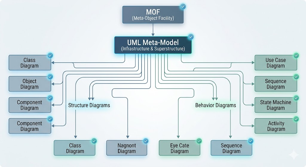
Figure 1: The underlying meta-model that supports the various UML diagram types.
The governance of UML falls under the Object Management Group (OMG), an open consortium dedicated to building standards that support interoperability, particularly for object-oriented systems. The OMG, perhaps best known for the CORBA (Common Object Request Broker Architecture) standards, ensured that UML remained an open standard. This openness allowed it to supersede the myriad of competing proprietary modeling languages that existed prior to 1997, creating a unified vocabulary for developers worldwide.
By far the most common usage of UML in modern agile environments is "UML as Sketch." In this mode, the primary goal is communication, not completeness.
* Selectivity: Developers only model specific aspects of the system that are complex or require discussion. * Informality: Strict adherence to UML syntax is often relaxed in favor of speed and clarity. * Collaboration: Sketches are typically created in real-time during team discussions, often on whiteboards.
In forward engineering, sketches are used to rough out ideas before coding begins. For example, a team might spend 10 minutes sketching a class diagram to discuss how a new feature will interact with existing modules. The goal is to visualize alternatives and reach a consensus quickly. These sketches are ephemeral; once the code is written, the diagram often serves no further purpose.

Sketches are also valuable for understanding legacy code. When digging into an unfamiliar codebase, a developer might draw a quick sequence diagram to trace the flow of execution for a specific use case. This reverse-engineered sketch highlights only the relevant classes and interactions, ignoring the rest of the system to reduce cognitive load.
Key Takeaway: Sketches are explorative. They are tools for thinking and talking, not for archiving.
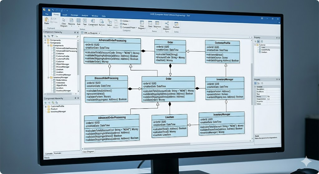
In contrast to sketching, "UML as Blueprint" focuses on completeness and precision. This approach mirrors traditional engineering disciplines, such as civil or mechanical engineering, where detailed drawings are handed off to construction teams.
* Completeness: The model aims to capture all design decisions, leaving little room for interpretation. * Formality: Strict adherence to UML syntax is required to ensure accuracy. * Tooling: Requires sophisticated Computer-Aided Software Engineering (CASE) tools with repositories to manage the complexity.
In this scenario, a senior designer or architect creates a detailed model that serves as a specification for programmers. The programmer’s role becomes more mechanical, translating the visual model into code. This approach is often used in large-scale enterprise systems where consistency and strict interface definitions are critical.
Blueprints are also used to document existing systems. Reverse-engineering tools can scan source code and generate detailed UML diagrams, providing a graphical browser for the codebase. Advanced tools offer "round-trip engineering," where changes in the code update the model, and changes in the model update the code.
Some modern tools integrate directly with IDEs, treating the source code as the repository and the UML diagrams as dynamic viewports. These "tripless" tools blur the line between modeling and coding, allowing developers to navigate complex systems visually without maintaining separate documentation.
Key Takeaway: Blueprints are definitive. They serve as a contract between designers and implementers.
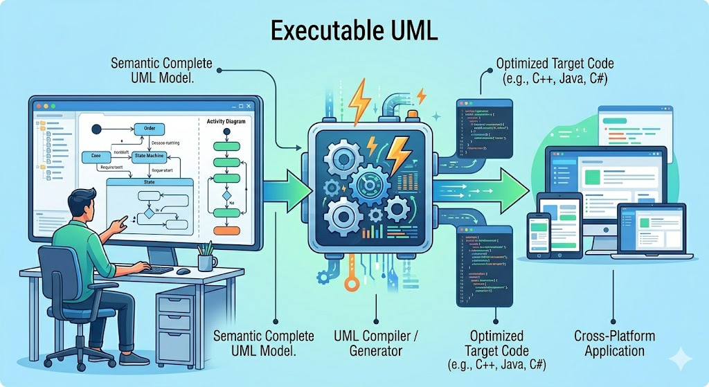
The third mode represents the highest level of abstraction, where the distinction between model and code disappears. In "UML as Programming Language," the models themselves are executable.
* Automation: Code generation is not just a helper; it is the primary mechanism for producing software. * Precision: The UML model must be semantically complete, containing all logic required for execution. * Tooling: Demands highly sophisticated compilers that can translate UML elements directly into binary or intermediate code.
In this mode, the concepts of forward and reverse engineering become obsolete. Since the UML model is the source code, there is no translation gap. Developers manipulate the system entirely through graphical interfaces or model-based editors. While this approach promises high productivity and platform independence, it requires significant investment in tooling and a shift in developer mindset.
Key Takeaway: Executable UML is transformative. It shifts the developer's role from writing code to designing logical structures.
The choice between Sketch, Blueprint, and Programming Language depends on several factors:
| Feature | UML as Sketch | UML as Blueprint | UML as Programming Language |
| Primary Goal | Communication & Exploration | Specification & Documentation | Automation & Execution |
| Completeness | Selective & Partial | Comprehensive & Detailed | Complete & Executable |
| Formality | Low | High | Very High |
| Tooling | Whiteboard, Lightweight Drawings | CASE Tools, Repositories | Advanced Compilers, MDA Tools |
| Best For | Agile Teams, Complex Logic Discussions | Large Enterprise Systems, Regulatory Compliance | Domain-Specific Platforms, Model-Driven Arch. |
The Unified Modeling Language is not a one-size-fits-all solution. Its versatility is both its greatest strength and the source of much industry confusion. By recognizing the three distinct modes of usage—Sketch, Blueprint, and Programming Language—teams can apply UML more effectively.
For most modern software teams, UML as Sketch offers the highest return on investment, facilitating rapid communication and shared understanding without the overhead of rigorous documentation. UML as Blueprint remains vital for large-scale, safety-critical, or highly regulated systems where precision and traceability are paramount. Finally, UML as Programming Language represents a niche but powerful approach for specific domains where model-driven architecture can significantly accelerate development.
Ultimately, the effectiveness of UML lies not in the diagrams themselves, but in how well they serve the development process. Whether used to spark a conversation on a whiteboard or to generate executable code, UML remains an indispensable tool in the software engineer’s toolkit.