In the fast-paced world of Agile development, teams often view UML (Unified Modeling Language) as heavyweight documentation that contradicts Agile principles. However, when used strategically, UML diagrams become powerful communication tools that enhance collaboration, clarify requirements, and prevent costly misunderstandings. This case study demonstrates how Agile teams can leverage lightweight UML modeling to accelerate delivery while maintaining architectural integrity. Through practical examples and PlantUML code, we'll explore how to integrate visual modeling into your sprint cycles without sacrificing velocity.
Agile teams should create UML diagrams that serve immediate needs—clarifying complex logic, onboarding new team members, or documenting architectural decisions—rather than comprehensive specifications.
Diagrams must evolve with the code. Using tools like PlantUML allows diagrams to be version-controlled alongside source code, ensuring they remain current.
Create diagrams during refinement sessions or architectural spikes, not in isolation. The process of building the model together is often more valuable than the diagram itself.
Choose diagram types based on the audience and message: use sequence diagrams for workflow clarity, class diagrams for domain understanding, and state machines for complex object lifecycles.
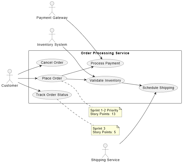
Scenario: An Agile team is building an order processing microservice for an e-commerce platform. The system must handle order creation, payment processing, inventory validation, and shipping coordination.
This diagram helps the Product Owner and team visualize scope and prioritize features for upcoming sprints.
@startuml
left to right direction
skinparam packageStyle rectangle

actor "Customer" as Customer
actor "Payment Gateway" as Payment
actor "Inventory System" as Inventory
actor "Shipping Service" as Shipping

rectangle "Order Processing Service" {
  usecase "Place Order" as UC1
  usecase "Process Payment" as UC2
  usecase "Validate Inventory" as UC3
  usecase "Schedule Shipping" as UC4
  usecase "Track Order Status" as UC5
  usecase "Cancel Order" as UC6
}

Customer --> UC1
Customer --> UC5
Customer --> UC6

UC1 --> UC2
UC1 --> UC3
UC3 --> UC4

Payment --> UC2
Inventory --> UC3
Shipping --> UC4

note right of UC1
  Sprint 1-2 Priority
  Story Points: 13
end note

note right of UC5
  Sprint 3
  Story Points: 5
end note
@enduml
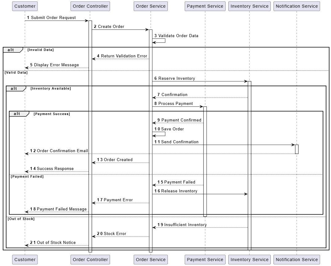
This diagram clarifies the interaction flow for the "Place Order" user story, helping developers understand dependencies and edge cases.
@startuml
autonumber
participant "Customer" as Customer
participant "Order Controller" as OrderCtrl
participant "Order Service" as OrderSvc
participant "Payment Service" as PaySvc
participant "Inventory Service" as InvSvc
participant "Notification Service" as NotifSvc

Customer -> OrderCtrl: Submit Order Request
activate OrderCtrl
OrderCtrl -> OrderSvc: Create Order
activate OrderSvc

OrderSvc -> OrderSvc: Validate Order Data
alt Invalid Data
  OrderSvc --> OrderCtrl: Return Validation Error
  OrderCtrl --> Customer: Display Error Message
else Valid Data
  OrderSvc -> InvSvc: Reserve Inventory
  activate InvSvc

  alt Inventory Available
    InvSvc --> OrderSvc: Confirmation
    OrderSvc -> PaySvc: Process Payment
    activate PaySvc

    alt Payment Success
      PaySvc --> OrderSvc: Payment Confirmed
      OrderSvc -> OrderSvc: Save Order
      OrderSvc -> NotifSvc: Send Confirmation
      activate NotifSvc
      NotifSvc --> Customer: Order Confirmation Email
      deactivate NotifSvc
      OrderSvc --> OrderCtrl: Order Created
      OrderCtrl --> Customer: Success Response
    else Payment Failed
      PaySvc --> OrderSvc: Payment Failed
      OrderSvc -> InvSvc: Release Inventory
      OrderSvc --> OrderCtrl: Payment Error
      OrderCtrl --> Customer: Payment Failed Message
    end
    deactivate PaySvc
  else Out of Stock
    InvSvc --> OrderSvc: Insufficient Inventory
    OrderSvc --> OrderCtrl: Stock Error
    OrderCtrl --> Customer: Out of Stock Notice
  end
  deactivate InvSvc
end

deactivate OrderSvc
deactivate OrderCtrl
@enduml
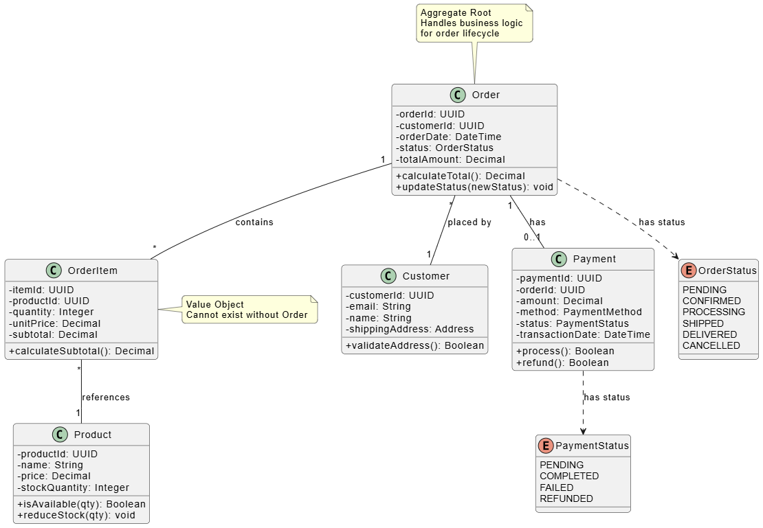
This diagram establishes the domain model during architectural spikes, ensuring all team members share a common understanding of entities and relationships.
@startuml
skinparam classAttributeIconSize 0
skinparam roundcorner 10

class "Order" {
  -orderId: UUID
  -customerId: UUID
  -orderDate: DateTime
  -status: OrderStatus
  -totalAmount: Decimal
  +calculateTotal(): Decimal
  +updateStatus(newStatus): void
}

class "OrderItem" {
  -itemId: UUID
  -productId: UUID
  -quantity: Integer
  -unitPrice: Decimal
  -subtotal: Decimal
  +calculateSubtotal(): Decimal
}

class "Product" {
  -productId: UUID
  -name: String
  -price: Decimal
  -stockQuantity: Integer
  +isAvailable(qty): Boolean
  +reduceStock(qty): void
}

class "Customer" {
  -customerId: UUID
  -email: String
  -name: String
  -shippingAddress: Address
  +validateAddress(): Boolean
}

class "Payment" {
  -paymentId: UUID
  -orderId: UUID
  -amount: Decimal
  -method: PaymentMethod
  -status: PaymentStatus
  -transactionDate: DateTime
  +process(): Boolean
  +refund(): Boolean
}

enum "OrderStatus" {
  PENDING
  CONFIRMED
  PROCESSING
  SHIPPED
  DELIVERED
  CANCELLED
}

enum "PaymentStatus" {
  PENDING
  COMPLETED
  FAILED
  REFUNDED
}

Order "1" -- "*" OrderItem : contains
OrderItem "*" -- "1" Product : references
Order "*" -- "1" Customer : placed by
Order "1" -- "0..1" Payment : has
Order ..> OrderStatus : has status
Payment ..> PaymentStatus : has status

note top of Order
  Aggregate Root
  Handles business logic
  for order lifecycle
end note

note right of OrderItem
  Value Object
  Cannot exist without Order
end note
@enduml
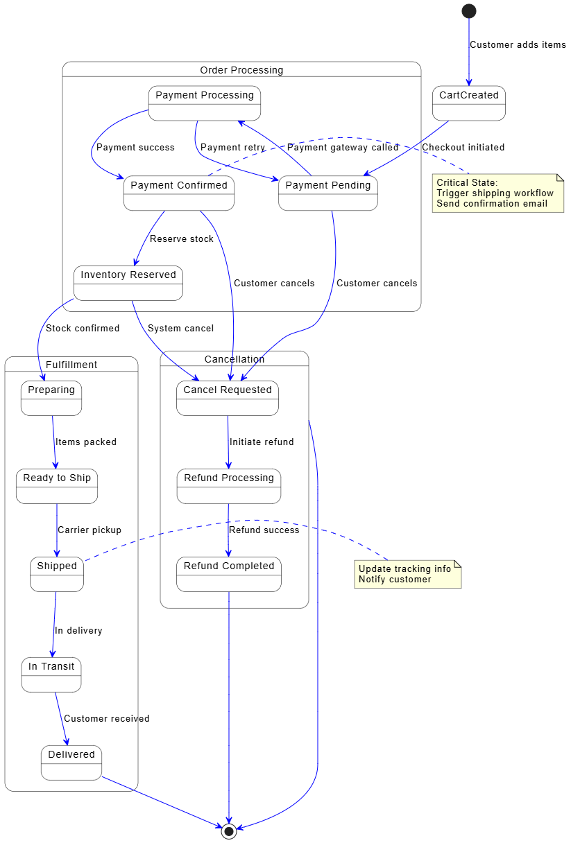
This diagram models the order lifecycle, helping QA teams identify test scenarios and developers implement state transitions correctly.
@startuml
skinparam state {
  BackgroundColor White
  BorderColor Black
  ArrowColor Blue
}

[*] --> CartCreated : Customer adds items

state "Order Processing" as Processing {
  state "Payment Pending" as PaymentPending
  state "Payment Processing" as PaymentProcessing
  state "Payment Confirmed" as PaymentConfirmed
  state "Inventory Reserved" as InventoryReserved
}

CartCreated --> PaymentPending : Checkout initiated
PaymentPending --> PaymentProcessing : Payment gateway called
PaymentProcessing --> PaymentConfirmed : Payment success
PaymentProcessing --> PaymentPending : Payment retry
PaymentConfirmed --> InventoryReserved : Reserve stock

state "Fulfillment" as Fulfillment {
  state "Preparing" as Preparing
  state "Ready to Ship" as ReadyShip
  state "Shipped" as Shipped
  state "In Transit" as InTransit
  state "Delivered" as Delivered
}

InventoryReserved --> Preparing : Stock confirmed
Preparing --> ReadyShip : Items packed
ReadyShip --> Shipped : Carrier pickup
Shipped --> InTransit : In delivery
InTransit --> Delivered : Customer received

state "Cancellation" as Cancelled {
  state "Cancel Requested" as CancelRequested
  state "Refund Processing" as RefundProcessing
  state "Refund Completed" as RefundComplete
}

PaymentPending --> CancelRequested : Customer cancels
PaymentConfirmed --> CancelRequested : Customer cancels
InventoryReserved --> CancelRequested : System cancel
CancelRequested --> RefundProcessing : Initiate refund
RefundProcessing --> RefundComplete : Refund success

Delivered --> [*]
RefundComplete --> [*]
Cancelled --> [*]

note right of PaymentConfirmed
  Critical State:
  Trigger shipping workflow
  Send confirmation email
end note

note left of Shipped
  Update tracking info
  Notify customer
end note
@enduml
This diagram helps the team visualize the workflow and identify bottlenecks during sprint planning.
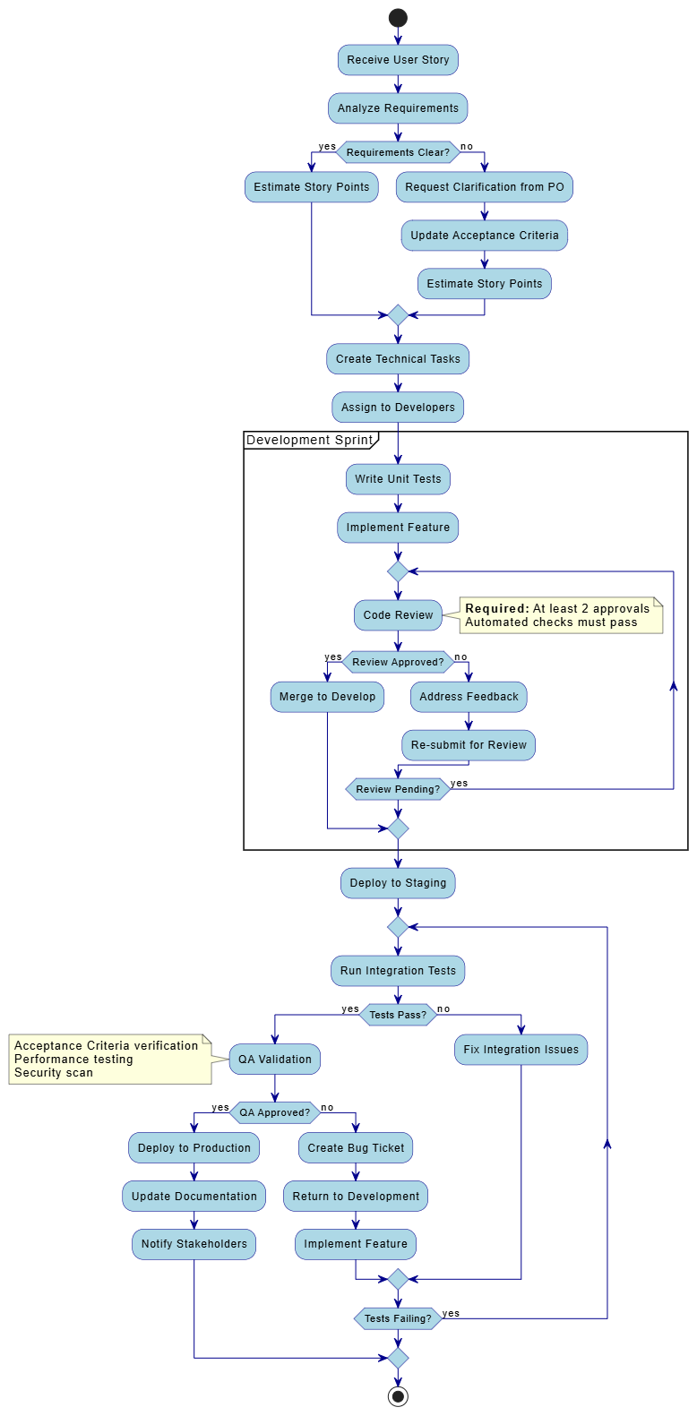
@startuml

skinparam activity {
  BackgroundColor LightBlue
  BorderColor DarkBlue
  ArrowColor DarkBlue
}

start
:Receive User Story;
:Analyze Requirements;

if (Requirements Clear?) then (yes)
  :Estimate Story Points;
else (no)
  :Request Clarification from PO;
  :Update Acceptance Criteria;
  :Estimate Story Points;
endif

:Create Technical Tasks;
:Assign to Developers;

partition "Development Sprint" {
  :Write Unit Tests;
  :Implement Feature;

  repeat
    :Code Review;
    note right
      **Required:** At least 2 approvals
      Automated checks must pass
    end note

    if (Review Approved?) then (yes)
      :Merge to Develop;
      break
    else (no)
      :Address Feedback;
      :Re-submit for Review;
    endif

  repeat while (Review Pending?) is (yes)
}

:Deploy to Staging;

repeat
  :Run Integration Tests;
  if (Tests Pass?) then (yes)
    :QA Validation;
    note left
      Acceptance Criteria verification
      Performance testing
      Security scan
    end note

    if (QA Approved?) then (yes)
      :Deploy to Production;
      :Update Documentation;
      :Notify Stakeholders;
      break
    else (no)
      :Create Bug Ticket;
      :Return to Development;
      :Implement Feature;
    endif
  else (no)
    :Fix Integration Issues;
  endif
repeat while (Tests Failing?) is (yes)
stop

@endumlThis diagram supports architectural discussions and helps teams understand service boundaries and dependencies.
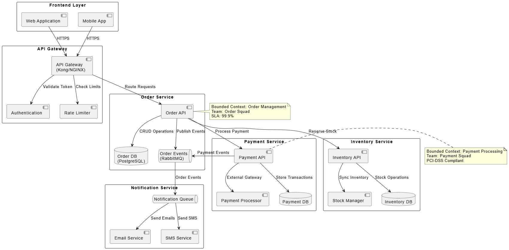
@startuml
skinparam componentStyle uml2
skinparam packageStyle rectangle

package "Frontend Layer" {
  component "Web Application" as WebApp
  component "Mobile App" as MobileApp
}

package "API Gateway" {
  component "API Gateway\n(Kong/NGINX)" as Gateway
  component "Authentication" as Auth
  component "Rate Limiter" as RateLimit
}

package "Order Service" {
  component "Order API" as OrderAPI
  database "Order DB\n(PostgreSQL)" as OrderDB
  queue "Order Events\n(RabbitMQ)" as OrderQueue
}

package "Payment Service" {
  component "Payment API" as PaymentAPI
  component "Payment Processor" as PayProcessor
  database "Payment DB" as PaymentDB
}

package "Inventory Service" {
  component "Inventory API" as InvAPI
  component "Stock Manager" as StockMgr
  database "Inventory DB" as InvDB
}

package "Notification Service" {
  component "Email Service" as EmailSvc
  component "SMS Service" as SMSSvc
  queue "Notification Queue" as NotifQueue
}

WebApp --> Gateway : HTTPS
MobileApp --> Gateway : HTTPS

Gateway --> Auth : Validate Token
Gateway --> RateLimit : Check Limits
Gateway --> OrderAPI : Route Requests

OrderAPI --> OrderDB : CRUD Operations
OrderAPI --> OrderQueue : Publish Events
OrderAPI --> PaymentAPI : Process Payment
OrderAPI --> InvAPI : Reserve Stock

PaymentAPI --> PayProcessor : External Gateway
PaymentAPI --> PaymentDB : Store Transactions
PaymentAPI --> OrderQueue : Payment Events

InvAPI --> InvDB : Stock Operations
InvAPI --> StockMgr : Sync Inventory

OrderQueue --> NotifQueue : Order Events
NotifQueue --> EmailSvc : Send Emails
NotifQueue --> SMSSvc : Send SMS

note right of OrderAPI
  Bounded Context: Order Management
  Team: Order Squad
  SLA: 99.9%
end note

note left of PaymentAPI
  Bounded Context: Payment Processing
  Team: Payment Squad
  PCI-DSS Compliant
end note
@enduml
UML modeling, when applied thoughtfully, complements Agile methodologies by providing visual clarity without bureaucratic overhead. This case study demonstrated how six core UML diagram types—use case, sequence, class, state machine, activity, and component diagrams—can address specific challenges in an e-commerce order processing system. By adopting a "just-enough" approach and leveraging text-based tools like PlantUML, Agile teams can create living documentation that evolves with the product, enhances cross-functional communication, and reduces technical debt. The key is to view UML not as a documentation burden but as a collaborative thinking tool that accelerates understanding and alignment across the team. Start small, focus on high-value diagrams, and let your team's needs guide your modeling practices.