What is Sequence Diagram?

What is Sequence Diagram?

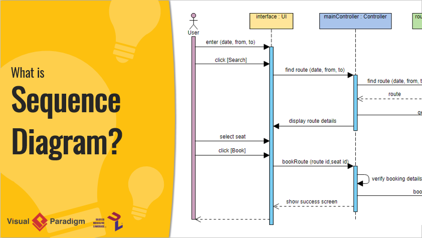
UML Sequence Diagrams are interaction diagrams that detail how operations are carried out. They capture the interaction between objects in the context of a collaboration. Sequence Diagrams are time focus and they show the order of the interaction visually by using the vertical axis of the diagram to represent time what messages are sent and when.

Sequence Diagram in UML Diagram Hierarchy

Sequence Diagrams captures:

  • the interaction that takes place in a collaboration that either realizes a use case or an operation (instance diagrams or generic diagrams)
  • high-level interactions between user of the system and the system, between the system and other systems, or between subsystems (sometimes known as system sequence diagrams)

Learn UML Faster, Better and Easier

Are you looking for a Free UML tool for learning UML faster, easier and quicker? Visual Paradigm Community Edition is a UML software that supports all UML diagram types. It is an international award-winning UML modeler, and yet it is easy-to-use, intuitive & completely free.

Free Download

Purpose of Sequence Diagram

  • Model high-level interaction between active objects in a system
  • Model the interaction between object instances within a collaboration that realizes a use case
  • Model the interaction between objects within a collaboration that realizes an operation
  • Either model generic interactions (showing all possible paths through the interaction) or specific instances of a interaction (showing just one path through the interaction)

Sequence Diagrams at a Glance

Sequence Diagrams show elements as they interact over time and they are organized according to object (horizontally) and time (vertically):

Object Dimension

  • The horizontal axis shows the elements that are involved in the interaction
  • Conventionally, the objects involved in the operation are listed from left to right according to when they take part in the message sequence. However, the elements on the horizontal axis may appear in any order

Time Dimension

  • The vertical axis represents time proceedings (or progressing) down the page.

Note that:

Time in a sequence diagram is all a about ordering, not duration. The vertical space in an interaction diagram is not relevant for the duration of the interaction.

Sequence Diagram Example: Hotel System

Sequence Diagram is an interaction diagram that details how operations are carried out -- what messages are sent and when. Sequence diagrams are organized according to time. The time progresses as you go down the page. The objects involved in the operation are listed from left to right according to when they take part in the message sequence.

Below is a sequence diagram for making a hotel reservation. The object initiating the sequence of messages is a Reservation window.

Sequence Diagram Example

Note That: Class and object diagrams are static model views. Interaction diagrams are dynamic. They describe how objects collaborate.

Sequence Diagram Notation

Notation Description Visual Representation

Actor

  • a type of role played by an entity that interacts with the subject (e.g., by exchanging signals and data)
  • external to the subject (i.e., in the sense that an instance of an actor is not a part of the instance of its corresponding subject).
  • represent roles played by human users, external hardware, or other subjects.

Note that:

  • An actor does not necessarily represent a specific physical entity but merely a particular role of some entity
  • A person may play the role of several different actors and, conversely, a given actor may be played by multiple different person.
Actor

Lifeline

  • A lifeline represents an individual participant in the Interaction.
Lifeline

Activations

  • A thin rectangle on a lifeline) represents the period during which an element is performing an operation.
  • The top and the bottom of the of the rectangle are aligned with the initiation and the completion time respectively
Activation

Call Message

  • A message defines a particular communication between Lifelines of an Interaction.
  • Call message is a kind of message that represents an invocation of operation of target lifeline.
Call Message

Return Message

  • A message defines a particular communication between Lifelines of an Interaction.
  • Return message is a kind of message that represents the pass of information back to the caller of a corresponded former message.
Return Message

Self Message

  • A message defines a particular communication between Lifelines of an Interaction.
  • Self message is a kind of message that represents the invocation of message of the same lifeline.
Self-Message

Recursive Message

  • A message defines a particular communication between Lifelines of an Interaction.
  • Recursive message is a kind of message that represents the invocation of message of the same lifeline. It's target points to an activation on top of the activation where the message was invoked from.
Recursive Message

Create Message

  • A message defines a particular communication between Lifelines of an Interaction.
  • Create message is a kind of message that represents the instantiation of (target) lifeline.
Create Message

Destroy Message

  • A message defines a particular communication between Lifelines of an Interaction.
  • Destroy message is a kind of message that represents the request of destroying the lifecycle of target lifeline.
Destroy Message

Duration Message

  • A message defines a particular communication between Lifelines of an Interaction.
  • Duration message shows the distance between two time instants for a message invocation.
Duration Message

Note

A note (comment) gives the ability to attach various remarks to elements. A comment carries no semantic force, but may contain information that is useful to a modeler.
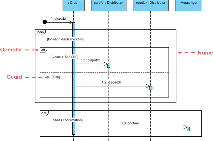
Note

Message and Focus of Control

  • An Event is any point in an interaction where something occurs.
  • Focus of control: also called execution occurrence, an execution occurrence
  • It shows as tall, thin rectangle on a lifeline)
  • It represents the period during which an element is performing an operation. The top and the bottom of the rectangle are aligned with the initiation and the completion time respectively.
Message and Focus of Control

Sequence Fragments

  • UML 2.0 introduces sequence (or interaction) fragments. Sequence fragments make it easier to create and maintain accurate sequence diagrams
  • A sequence fragment is represented as a box, called a combined fragment, which encloses a portion of the interactions within a sequence diagram
  • The fragment operator (in the top left cornet) indicates the type of fragment
  • Fragment types: ref, assert, loop, break, alt, opt, neg
Fragment
Operator Fragment Type
alt Alternative multiple fragments: only the one whose condition is true will execute.
opt Optional: the fragment executes only if the supplied condition is true. Equivalent to an alt only with one trace.
par Parallel: each fragment is run in parallel.
loop Loop: the fragment may execute multiple times, and the guard indicates the basis of iteration.
region Critical region: the fragment can have only one thread executing it at once.
neg Negative: the fragment shows an invalid interaction.
ref Reference: refers to an interaction defined on another diagram. The frame is drawn to cover the lifelines involved in the interaction. You can define parameters and a return value.
sd Sequence diagram: used to surround an entire sequence diagram.

Note That:

  • It is possible to combine frames in order to capture, e.g., loops or branches.
  • Combined fragment keywords: alt, opt, break, par, seq, strict, neg, critical, ignore, consider, assert and loop.
  • Constraints are usually used to show timing constraints on messages. They can apply to the timing of one message or intervals between messages.

Combined Fragment Example

Combined Fragment example

Sequence Diagram for Modeling Use Case Scenarios

User requirements are captured as use cases that are refined into scenarios. A use case is a collection of interactions between external actors and a system. In UML, a use case is:

"the specification of a sequence of actions, including variants, that a system (or entity) can perform, interacting with actors of the system."

A scenario is one path or flow through a use case that describes a sequence of events that occurs during one particular execution of a system which is often represented by a sequence diagram.

Sequence Diagram for Use Case

Sequence Diagram - Model before Code

Sequence diagrams can be somewhat close to the code level, so why not just code up that algorithm rather than drawing it as a sequence diagram?

  • A good sequence diagram is still a bit above the level of the real code
  • Sequence diagrams are language neutral
  • Non-coders can do sequence diagrams
  • Easier to do sequence diagrams as a team
  • Can be used for testing and/or UX Wireframing

Try to Draw UML Sequence Diagram Now

You've learned what a Sequence Diagram is and how to draw a Sequence Diagram. It's time to draw a Sequence Diagram of your own. Get Visual Paradigm Community Edition, a free UML modeling tool, and create your own Sequence Diagram with the free Sequence Diagram tool. It's easy-to-use and intuitive.

Free Download

Turn every software project into a successful one.

We use cookies to offer you a better experience. By visiting our website, you agree to the use of cookies as described in our Cookie Policy.

OK