
The Unified Modeling Language (UML) is the industry-standard visual language for software engineering. Standardized by the Object Management Group (OMG), UML is not a programming language; rather, it is a modeling language used to visualize, specify, construct, and document the artifacts of a software system.
Whether you are designing a microservices architecture, mapping out a user journey, or documenting a complex database schema, UML provides a universal vocabulary. It bridges the communication gap between business stakeholders, system architects, and software developers, ensuring that everyone shares the same mental model of the system before a single line of code is written.
UML is built upon a foundation of core concepts that dictate how we represent software systems. These are broadly categorized into Things (the building blocks), Relationships (how things connect), and Diagrams (the visual representations).
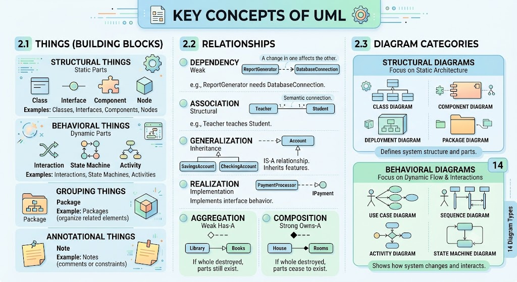
Structural Things: The static parts of a model. Examples: Classes, Interfaces, Components, Nodes.
Behavioral Things: The dynamic parts of a model. Examples: Interactions, State Machines, Activities.
Grouping Things: Organizational parts. Example: Packages (used to group related classes or diagrams).
Annotational Things: Explanatory parts. Example: Notes (used to add comments or constraints to a diagram).
Relationships define how the "Things" interact with one another.
Dependency (Weak Relationship): A change in one thing affects the other.
Example: A ReportGenerator class depends on a DatabaseConnection class because it needs it to fetch data, but it doesn't own it.
Association (Structural Relationship): A semantic connection between objects.
Example: A Teacher teaches a Student. Both have independent lifecycles.
Generalization (Inheritance): An "is-a" relationship where a specialized element inherits from a general element.
Example: A SavingsAccount is a BankAccount.
Realization (Implementation): A class implements the behavior defined by an interface.
Example: A PaymentProcessor class realizes/implements the IPayment interface.
Aggregation & Composition (Whole-Part):
Aggregation (Weak "has-a"): A Library has Books. If the library closes, the books still exist elsewhere.
Composition (Strong "owns-a"): A House has Rooms. If the house is destroyed, the rooms cease to exist.
UML 2.x defines 14 diagram types, split into two main categories:
Structural Diagrams: Focus on the static architecture (e.g., Class, Component, Deployment, Package diagrams).
Behavioral Diagrams: Focus on the dynamic flow and interactions (e.g., Use Case, Sequence, Activity, State Machine diagrams).
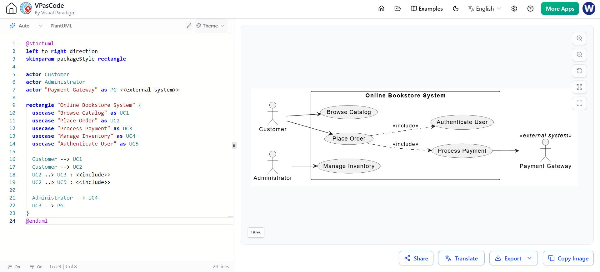
To illustrate these concepts, we will use a running example of an Online Bookstore System. Below are the most critical UML diagrams, complete with PlantUML code.
Purpose: Captures the functional requirements of a system from the user's perspective. It shows Actors (users or external systems) and Use Cases (system functionalities).
PlantUML Code:
@startuml
left to right direction
skinparam packageStyle rectangle

actor Customer
actor Administrator
actor "Payment Gateway" as PG <<external system>>

rectangle "Online Bookstore System" {
  usecase "Browse Catalog" as UC1
  usecase "Place Order" as UC2
  usecase "Process Payment" as UC3
  usecase "Manage Inventory" as UC4
  usecase "Authenticate User" as UC5

  Customer --> UC1
  Customer --> UC2
  UC2 ..> UC3 : <<include>>
  UC2 ..> UC5 : <<include>>

  Administrator --> UC4
  UC3 --> PG
}
@enduml
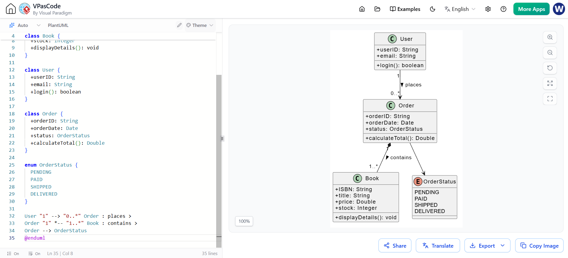
Purpose: Shows the static structure of the system, detailing classes, their attributes, methods, and the relationships between them. This is the backbone of object-oriented design.
PlantUML Code:
@startuml
skinparam classAttributeIconSize 0

class Book {
  +ISBN: String
  +title: String
  +price: Double
  +stock: Integer
  +displayDetails(): void
}

class User {
  +userID: String
  +email: String
  +login(): boolean
}

class Order {
  +orderID: String
  +orderDate: Date
  +status: OrderStatus
  +calculateTotal(): Double
}

enum OrderStatus {
  PENDING
  PAID
  SHIPPED
  DELIVERED
}

User "1" --> "0..*" Order : places >
Order "1" *-- "1..*" Book : contains >
Order --> OrderStatus
@enduml
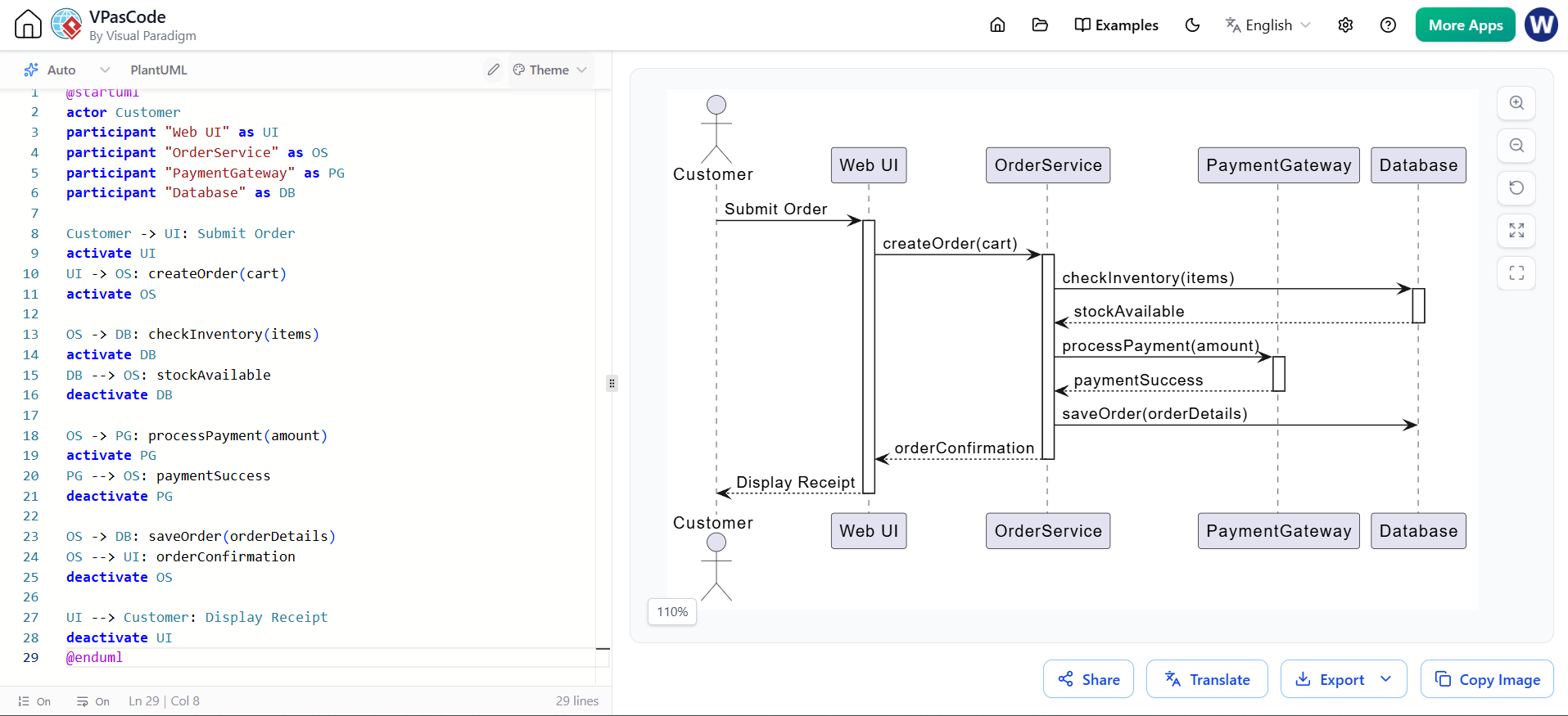
Purpose: Illustrates how objects interact with each other in a specific scenario over time. It is highly effective for detailing the logic of a single Use Case.
PlantUML Code:
@startuml
actor Customer
participant "Web UI" as UI
participant "OrderService" as OS
participant "PaymentGateway" as PG
participant "Database" as DB

Customer -> UI: Submit Order
activate UI
UI -> OS: createOrder(cart)
activate OS

OS -> DB: checkInventory(items)
activate DB
DB --> OS: stockAvailable
deactivate DB

OS -> PG: processPayment(amount)
activate PG
PG --> OS: paymentSuccess
deactivate PG

OS -> DB: saveOrder(orderDetails)
OS --> UI: orderConfirmation
deactivate OS

UI --> Customer: Display Receipt
deactivate UI
@enduml
Purpose: Represents the workflow or business process step-by-step. It is similar to a flowchart but supports parallel processing (concurrency) and complex decision logic.
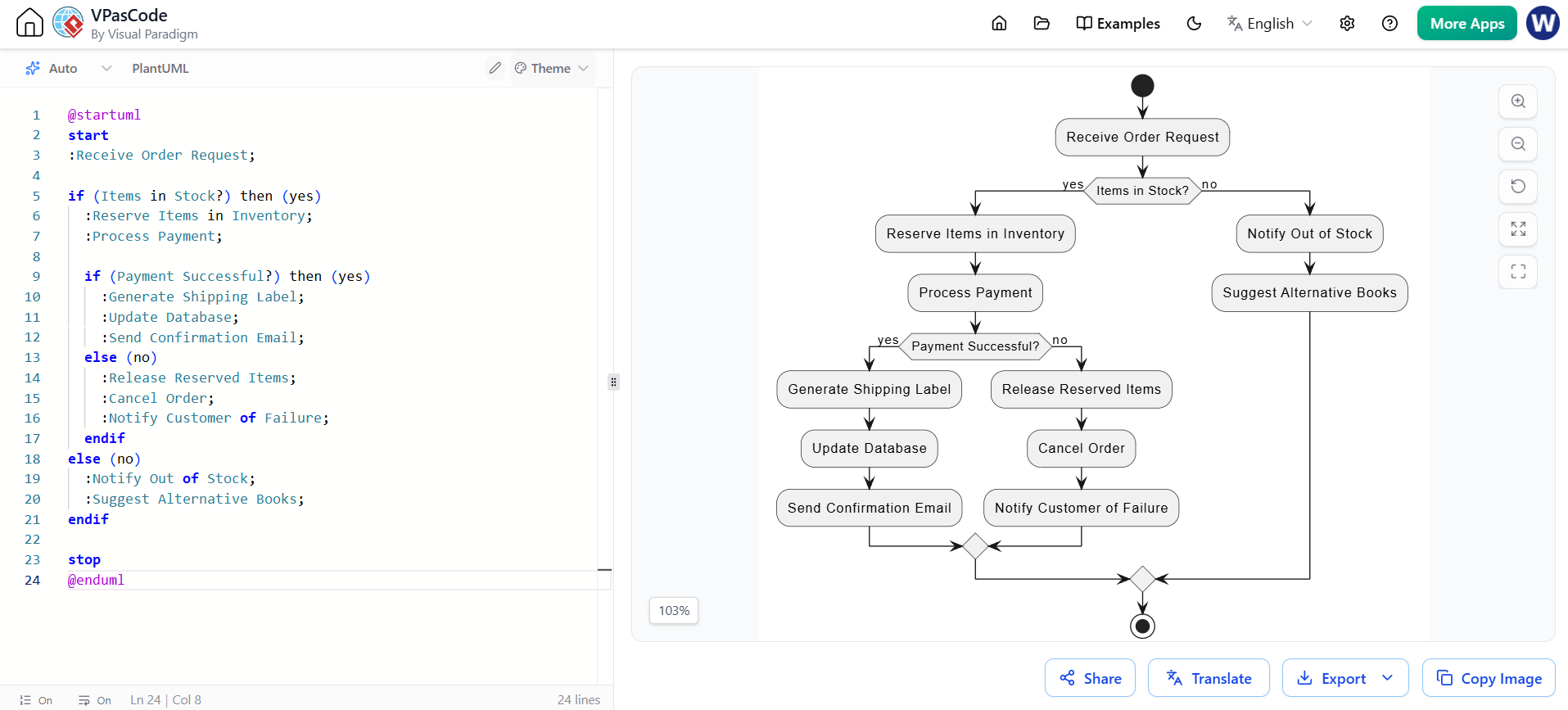
PlantUML Code:
@startuml
start
:Receive Order Request;

if (Items in Stock?) then (yes)
  :Reserve Items in Inventory;
  :Process Payment;

  if (Payment Successful?) then (yes)
    :Generate Shipping Label;
    :Update Database;
    :Send Confirmation Email;
  else (no)
    :Release Reserved Items;
    :Cancel Order;
    :Notify Customer of Failure;
  endif
else (no)
  :Notify Out of Stock;
  :Suggest Alternative Books;
endif

stop
@enduml
Purpose: Models the different states an object can be in during its lifecycle and the events that trigger transitions between those states.
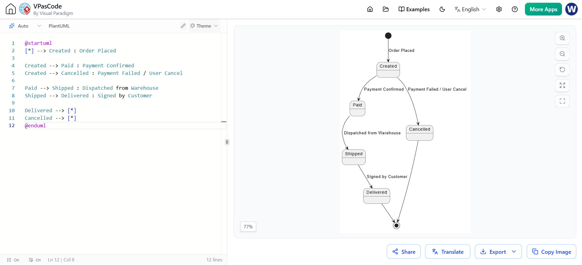
PlantUML Code:
@startuml
[*] --> Created : Order Placed

Created --> Paid : Payment Confirmed
Created --> Cancelled : Payment Failed / User Cancel

Paid --> Shipped : Dispatched from Warehouse
Shipped --> Delivered : Signed by Customer

Delivered --> [*]
Cancelled --> [*]
@enduml
To get the most out of UML without falling into the trap of "analysis paralysis," follow these industry best practices:
Model Iteratively (Agile Modeling): Do not try to model the entire system before coding. Model the architecture first, then model complex components iteratively as you develop them.
Know Your Audience: Use Use Case and Activity diagrams for business stakeholders and clients. Use Class, Sequence, and State diagrams for developers and architects.
Avoid Over-Modeling: UML should clarify, not complicate. You do not need to map every single getter and setter in a Class diagram. Focus on the core domain model and complex relationships.
Keep it Synchronized: Outdated diagrams are worse than no diagrams. Use tools that support round-trip engineering (generating code from diagrams and updating diagrams from code) to keep your models alive.
UML remains an indispensable tool in the software engineering toolkit. By providing a standardized, visual syntax, it allows teams to tackle complexity, validate architectural decisions, and ensure that business requirements are accurately translated into technical designs. While the rise of Agile and low-code platforms has shifted some focus away from heavy upfront documentation, the core principles of UML—specifically in modeling domain logic, system interactions, and state lifecycles—are more relevant than ever in the era of distributed microservices and AI-assisted development.
To effectively harness the power of UML, having the right tooling is crucial. While text-based tools like PlantUML are excellent for version control and rapid prototyping, enterprise teams often require robust, GUI-driven environments. Visual Paradigm stands out as a premier, comprehensive tool for UML modeling. It offers an extensive suite of all 14 UML diagram types, seamless code engineering (forward and reverse), real-time team collaboration features, and integration with popular Agile tools like Jira. Whether you are a solo developer sketching a quick sequence diagram or an enterprise architect designing a massive distributed system, Visual Paradigm provides the professional-grade environment needed to turn your UML models into successful software realities.

