In the complex world of software development, code alone is often insufficient to convey the grand design of a system. Before a single line of code is written, architects and developers must bridge the gap between abstract requirements and concrete implementation. This is where The Unified Modeling Language (UML) becomes an indispensable tool.
Based on the foundational principles of The UML User Guide, this tutorial is designed to help you transition from thinking purely in code to visualizing system architecture. By creating models—simplifications of reality—we can better understand, specify, construct, and document the systems we build. Whether you are a seasoned developer looking to refine your architectural communication or a beginner taking your first steps into system design, mastering the core building blocks of UML will empower you to create clearer, more robust software solutions.
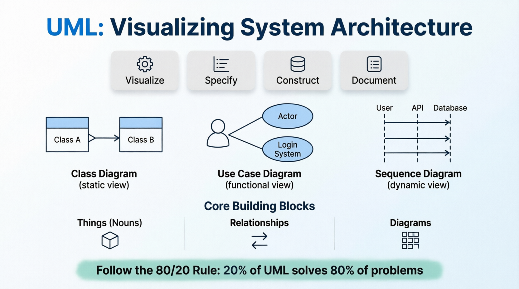
A model is not the system itself; it is a simplification of reality created to enhance understanding. Just as an architect uses blueprints before laying bricks, software engineers use models to navigate complexity. Modeling helps you achieve four primary aims:
Visualize: See the system as it currently exists or as you envision it becoming.
Specify: Define the structure or behavior of a system with precision, reducing ambiguity.
Construct: Create a template or blueprint that guides the actual coding and implementation process.
Document: Record the critical decisions made during design for future reference, maintenance, and onboarding.
The UML vocabulary is constructed from three fundamental categories: Things, Relationships, and Diagrams. Understanding these "nouns" and "verbs" of modeling is essential for reading and creating effective diagrams.
These represent the static parts of a model.
Class: A description of a set of objects that share the same attributes, operations, relationships, and semantics.
Interface: A collection of operations that specify a service or contract provided by a class or component.
Component: A physical, replaceable part of a system that conforms to and provides the realization of a set of interfaces (e.g., a DLL, Java Bean, or microservice).
Node: A physical element that exists at run-time and represents a computational resource, such as a server, device, or execution environment.
These represent the dynamic parts of a model over time.
Interaction: A behavior consisting of messages exchanged among objects within a particular context to accomplish a specific purpose.
State Machine: A behavior that specifies the sequences of states an object goes through during its lifetime in response to events.
These connect the things together, defining how they interact and depend on one another.
Dependency: A "using" relationship. If one thing changes, it may affect the other. It is typically represented by a dashed arrow.
Association: A structural relationship describing links between objects. It represents a "has-a" or "uses-a" connection.
Generalization: An "is-a-kind-of" relationship, commonly known as inheritance. It allows specialized elements to inherit features from more general ones.
Realization: A semantic relationship where one element (like a class) implements the contract specified by another (like an interface).
While UML offers many diagram types, beginners can achieve significant clarity by mastering just three essential views: the Static View, the Functional View, and the Dynamic View.
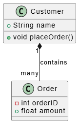
The Class Diagram is the most common UML diagram. It visualizes the static design of a system, showing classes, their attributes, methods, and the relationships between them.
PlantUML Example:
PlantUML code:
@startuml
class Customer {
  +String name
  +void placeOrder()
}

class Order {
  -int orderID
  +float amount
}

Customer "1" *-- "many" Order : contains
@enduml
(Note: In a full visual editor like Visual Paradigm, this code renders a clear diagram showing the Customer class linked to the Order class via a composition relationship.)
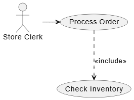
Use Case Diagrams capture the intended behavior of the system from the perspective of external users, known as Actors. They are excellent for high-level requirement gathering and stakeholder communication.
PlantUML Example:
PlantUML Example
@startuml
actor "Store Clerk" as Clerk
usecase "Process Order" as UC1
usecase "Check Inventory" as UC2

Clerk -> UC1
UC1 ..> UC2 : <<include>>
@enduml
(Note: This diagram illustrates how the "Store Clerk" actor initiates the "Process Order" use case, which inherently includes the "Check Inventory" function.)
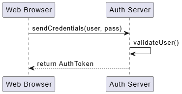
Sequence Diagrams are interaction diagrams that emphasize the time ordering of messages exchanged between objects. They are crucial for understanding complex logic flows and API interactions.
PlantUML Example:
PlantUML Example
@startuml
participant "Web Browser" as Browser
participant "Auth Server" as Server

Browser -> Server : sendCredentials(user, pass)
Server -> Server : validateUser()
Server --> Browser : return AuthToken
@enduml
(Note: This visualization clearly shows the chronological flow of authentication, from the browser sending credentials to the server validating them and returning a token.)
To ensure your models remain useful rather than burdensome, follow these best practices:
Follow the 80/20 Rule: You can solve 80% of modeling problems using only 20% of UML. Focus on basic classes, use cases, and associations before diving into obscure diagram types.
Balanced Classes: Avoid "God Classes" that do too much (hard to reuse) or overly fragmented classes (hard to manage). Every class should adhere to the Single Responsibility Principle.
Naming Conventions: Maintain consistency. Capitalize the first letter of every word in a class name (e.g., TemperatureSensor, UserProfile) to improve readability.
Avoid Clutter: Do not attempt to show every single attribute or relationship in one diagram. Focus on one aspect or "view" at a time. If a diagram becomes crowded, split it into multiple focused diagrams.
Use Notes as Review Tools: Treat Notes as electronic sticky notes. Use them to keep track of work in progress, ask questions, or document design decisions directly on the canvas.
AI Relevance: Leverage AI tools to generate initial PlantUML snippets from natural language requirements. However, always refine them manually in professional tools like Visual Paradigm to ensure the "semantic backplane" remains consistent across the entire project.
Aesthetics matter in modeling because clarity drives understanding. Apply these visual techniques to enhance your diagrams:
Minimizing Crossing Lines: Always lay out your diagram elements to minimize lines that cross. Crossed lines create visual noise and make it difficult to trace relationships.
Spatial Organization: Place elements that are semantically close (such as a parent class and its children, or related components) physically close to each other on the canvas.
Extensibility with Stereotypes: If standard UML symbols aren't enough, use Stereotypes (keywords in guillemets like «exception» or «microservice») to create new building blocks tailored to your specific project domain.
Mastering UML is not about memorizing every symbol in the specification; it is about adopting a mindset of clarity and precision. By utilizing the core building blocks of Things, Relationships, and Diagrams, you can transform abstract ideas into concrete visualizations that guide development and facilitate communication.
Remember to start simple. Focus on the essential diagrams—Class, Use Case, and Sequence—to cover the majority of your architectural needs. As you grow more comfortable, you can explore advanced features and stereotypes to tailor your models to modern complexities like cloud infrastructure and microservices. Ultimately, a well-crafted model is a powerful tool that saves time, reduces errors, and ensures that everyone involved in the project shares a common understanding of the system's vision.