UML Use Case Diagram Notations Guide
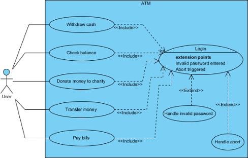 |
| Sample UML use case diagram |
Use case diagram is a kind of UML diagram. Here is a list of Unified Modeling Language (UML) notations supported in a UML use case diagram:
|
||||||||||||||||||||||
| List of UML notations available in UML use case diagram |
Use Case
| UML use case |
A use case represents a user goal that can be achieved by accessing the system or software application. In Visual Paradigm, you can make use of the sub-diagram feature to describe the interaction between user and system within a use case by creating a sub-sequence diagram under a use case. You can also describe the use case scenario using the Flow of Events editor.
OMG UML Specification
What is a use case in UML? According to the OMG Unified Modeling Language (OMG UML) specification (UML Superstructure Specification version 2.4.1, page 606), use case is:
Association
 |
| UML association |
Actor and use case can be associated to indicate that the actor participates in that use case. Therefore, an association correspond to a sequence of actions between the actor and use case in achieving the use case.
OMG UML Specification
What is an association in UML? According to the OMG Unified Modeling Language (OMG UML) specification (UML Superstructure Specification version 2.4.1, page 36), association is:
...
An association specifies a semantic relationship that can occur between typed instances. It has at least two ends represented by properties, each of which is connected to the type of the end. More than one end of the association may have the same type.
An end property of an association that is owned by an end class or that is a navigable owned end of the association indicates that the association is navigable from the opposite ends; otherwise, the association is not navigable from the opposite ends.
Actor
| UML actor |
Actors are the entities that interact with a system. Although in most cases, actors are used to represent the users of system, actors can actually be anything that needs to exchange information with the system. So, an actor may be people, computer hardware, other systems, etc.
Note that actor represents a role that a user can play but not a specific user. So, in a hospital information system, you may have doctor and patient as actors but not Dr. John, Mrs. Brown as actors.
OMG UML Specification
What is an actor in UML? According to the OMG Unified Modeling Language (OMG UML) specification (UML Superstructure Specification version 2.4.1), actor is:
...
An Actor models a type of role played by an entity that interacts with the subject (e.g., by exchanging signals and data) but which is external to the subject (i.e. in the sense that an instance of an actor is not a part of the instance of its corresponding subject). Actors may represent roles played by human users, external hardware, or other subjects. Note that an actor does not necessarily represent a specific physical entity but merely a particular facet (i.e."role") of some entity that is relevant to the specification of its associated use cases. Thus, a single physical instance may play the role of several different actors and conversely, a given actor may be played by multiple different instances.
System
 |
| UML system |
The scope of a system can be represented by a system (shape), or sometimes known as a system boundary. The use cases of the system are placed inside the system shape, while the actor who interact with the system are put outside the system. The use cases in the system make up the total requirements of the system.
OMG UML Specification
What is a system in UML? According to the OMG Unified Modeling Language (OMG UML) specification (UML Superstructure Specification version 2.4.1, page 608), system is:
Include
 |
| UML include |
An include relationship specifies how the behavior for the inclusion use case is inserted into the behavior defined for the base use case.
OMG UML Specification
What is an include in UML? According to the OMG Unified Modeling Language (OMG UML) specification (UML Superstructure Specification version 2.4.1, page 604), include is:
Extend
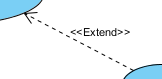 |
| UML extend |
An extend relationship specifies how the behavior of the extension use case can be inserted into the behavior defined for the base use case.
OMG UML Specification
What is an extend in UML? According to the OMG Unified Modeling Language (OMG UML) specification (UML Superstructure Specification version 2.4.1, page 601), extend is:
...
This relationship specifies that the behavior of a use case may be extended by the behavior of another (usually supplementary) use case. The extension takes place at one or more specific extension points defined in the extended use case. Note, however, that the extended use case is defined independently of the extending use case and is meaningful independently of the extending use case. On the other hand, the extending use case typically defines behavior that may not necessarily be meaningful by itself. Instead, the extending use case defines a set of modular behavior increments that augment an execution of the extended use case under specific conditions.
Note that the same extending use case can extend more than one use case. Furthermore, an extending use case may itself be extended.
Dependency
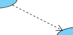 |
| UML dependency |
A dependency relationship represents that a model element relies on another model element for specification and/or implementation.
OMG UML Specification
What is a dependency in UML? According to the OMG Unified Modeling Language (OMG UML) specification (UML Superstructure Specification version 2.4.1, page 61), dependency is:
Generalization
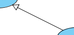 |
| UML generalization |
A generalization relationship is used to represent inheritance relationship between model elements of same type. The more specific model element share the same specification with. the more general the model element but carries more details in extra.
OMG UML Specification
What is a generalization in UML? According to the OMG Unified Modeling Language (OMG UML) specification (UML Superstructure Specification version 2.4.1, page 70), generalization is:
Realization
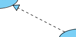 |
| UML realization |
A realization is a relationship between a specification and its implementation.
OMG UML Specification
What is a realization in UML? According to the OMG Unified Modeling Language (OMG UML) specification (UML Superstructure Specification version 2.4.1, page 131), realization is:
Collaboration
 |
| UML collaboration |
OMG UML Specification
What is a collaboration in UML? According to the OMG Unified Modeling Language (OMG UML) specification (UML Superstructure Specification version 2.4.1, page 174), collaboration is:
Related Resources
The following resources may help you to learn more about the topic discussed in this page.
| 1. Drawing use case diagrams | Table of Contents | 3. Documenting use case details |