
Here are some questions that have been asked frequently in the UML world are: What is a use case diagram? Why Use case diagram? or simply, Why use cases?. Some people don't know what use case is, while the rest under-estimated the usefulness of use cases in developing a good software product. Is use case diagram underrated? I hope you will find the answer when finished reading this article.
So what is a use case diagram? A UML use case diagram is the primary form of system/software requirements for a new software program underdeveloped. Use cases specify the expected behavior (what), and not the exact method of making it happen (how). Use cases once specified can be denoted both textual and visual representation (i.e. use case diagram). A key concept of use case modeling is that it helps us design a system from the end user's perspective. It is an effective technique for communicating system behavior in the user's terms by specifying all externally visible system behavior.
A use case diagram is usually simple. It does not show the detail of the use cases:
As said, a use case diagram should be simple and contains only a few shapes. If yours contain more than 20 use cases, you are probably misusing use case diagram.
The figure below shows the UML diagram hierarchy and the positioning of the UML Use Case Diagram. As you can see, use case diagrams belong to the family of behavioral diagrams.

Note that:
Are you looking for a Free UML tool for learning UML faster, easier and quicker? Visual Paradigm Community Edition is a UML software that supports all UML diagram types. It is an international award-winning UML modeler, and yet it is easy-to-use, intuitive & completely free.
Free DownloadThese days use case modeling is often associated with UML, although it has been introduced before UML existed. Its brief history is as follow:
Use case diagrams are typically developed in the early stage of development and people often apply use case modeling for the following purposes:
A standard form of use case diagram is defined in the Unified Modeling Language as shown in the Use Case Diagram example below:
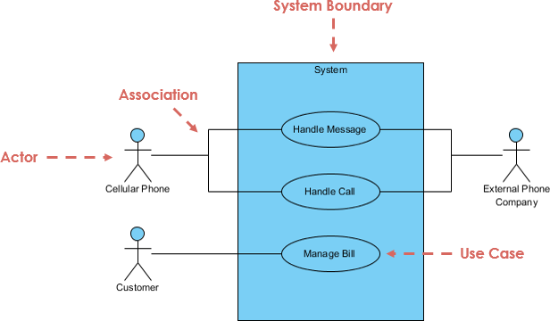
| Notation Description | Visual Representation |
|---|---|
Actor
|
 |
Use Case
|
 |
Communication Link
|
 |
Boundary of system
|
 |
Use cases share different kinds of relationships. Defining the relationship between two use cases is the decision of the software analysts of the use case diagram. A relationship between two use cases is basically modeling the dependency between the two use cases. The reuse of an existing use case by using different types of relationships reduces the overall effort required in developing a system. Use case relationships are listed as the following:
| Use Case Relationship | Visual Representation |
|---|---|
Extends
|
 |
Include
|
 |
Generalization
|
 |
Identifying actors and use cases is the first step in successful system design. Visual Paradigm’s AI ecosystem streamlines this process—from initial brainstorming in Desktop and Chatbot to sophisticated, automated workflows in our Web Apps.
🛠️ Use Case Modeling Studio: End-to-end AI workspace from scope definition to full Software Design Documents.
📝 Description Generator: Instantly transform problem domains into specifications and PlantUML diagrams.
⚡ Refinement Tool: Automatically apply UML best practices and <<include>>/<<extend>> relationships.
🔄 Use Case to Activity: Bridges textual elaboration to visual behavioral modeling with AI.
📋 Report Generator: Turns visual diagrams into structured, detailed Markdown documentation.
A Use Case diagram illustrates a set of use cases for a system, i.e. the actors and the relationships between the actors and use cases.

The include relationship adds additional functionality not specified in the base use case. The <<Include>> relationship is used to include common behavior from an included use case into a base use case in order to support the reuse of common behavior.

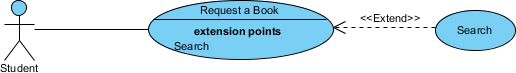
The extend relationships are important because they show optional functionality or system behavior. The <<extend>> relationship is used to include optional behavior from an extending use case in an extended use case. Take a look at the use case diagram example below. It shows an extend connector and an extension point "Search".
A generalization relationship means that a child use case inherits the behavior and meaning of the parent use case. The child may add or override the behavior of the parent. The figure below provides a use case example by showing two generalization connectors that connect between the three use cases.

The figure below shows a use case diagram example for a vehicle system. As you can see even a system as big as a vehicle sales system contains not more than 10 use cases! That's the beauty of use case modeling.
The use case model also shows the use of extend and include. Besides, there are associations that connect between actors and use cases.

Often, people find it easiest to start the requirements elicitation process by identifying the actors. The following questions can help you identify the actors of your system (Schneider and Winters - 1998):
Identifying the Use Cases, and then the scenario-based elicitation process carries on by asking what externally visible, observable value that each actor desires. The following questions can be asked to identify use cases, once your actors have been identified (Schneider and Winters - 1998):
Now, check the tips below to see how to apply use case effectively in your software project.
Use case granularity refers to the way in which information is organized within use case specifications, and to some extent, the level of detail at which they are written. Achieving the right level of use case granularity eases communication between stakeholders and developers and improves project planning.
Alastair Cockburn in Writing Effective Use Cases gives us an easy way to visualize different levels of goal level by thinking in terms of the sea:

Note that:
I hope you can answer "what is use case diagram" now and can apply use case in your project. If you want to learn more about other UML diagram types, please check the UML guide: Overview of the 14 UML Diagram Types.
You've learned what a Use Case Diagram is and how to draw a Use Case Diagram. It's time to draw a Use Case Diagram of your own. Get Visual Paradigm Community Edition, a free UML software, and create your own Use Case Diagram with the free Use Case Diagram tool. It's easy-to-use and intuitive.
Free Download