Activity Diagrams consist of activities, states and transitions between activities and states which describe how activities are coordinated to provide a service, such as, how the events in a single use case relate to one another, or how a collection of use cases coordinate to create a workflow for an organisation
Steps to develop Activity Diagrams
The steps below outline the major steps to take in creating a UML Activity Diagram.
- Finding system Actors, Classes and use cases
- Identifying key scenarios of system use cases
- Combining the scenarios to produce comprehensive workflows described using activity diagrams
- Where significant object behavior is triggered by a workflow, adding object flows to the diagrams
- Where workflows cross technology boundaries, using swimlanes to map the activities
- Refining complicated high level activities similarly, nested activity diagrams
Creating an Activity Diagram
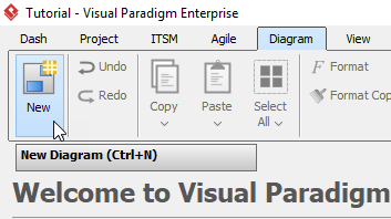
- Click New > New Diagram form the toolbar.
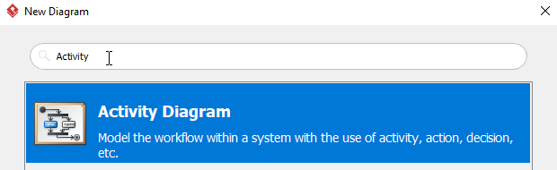
- In the New Diagram window, select Activity Diagram, then click Next. You can use the search bar above to filter diagrams.
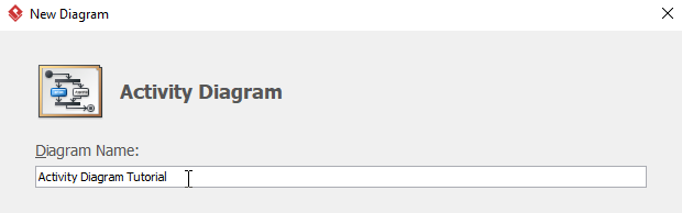
- Name the diagram, then click OK. In this tutorial, the diagram will be named Activity Diagram Tutorial. You will then see an empty diagram.
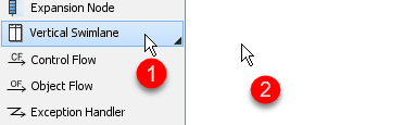
- Select Vertical Swimlane, then click any empty space on the diagram.
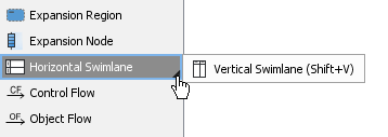
If you cannot findVertical Swimlane, try click the small triangle next to Horizontal Swimelane, you will then see Vertical Swimlane.
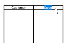
- You can rename partitions by double clicking the name of each partition. The first two participants in this tutorial are Customer and Sales.
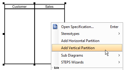
- To create more partitions, right click any empty space on the swimlane, then select Add Vertical Partition.
- Repeat step 6 for more partitions.
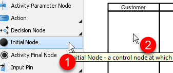
- Create the initial node by selecting Initial Node, then click on the participant where you want the activity starts. In this tutorial, we would like like the activity starts from the Customer participant.
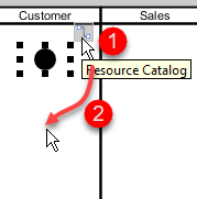
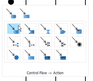
- To create an action, click the initial node, click and hold the resource button, then drag to the desire location. When release the button, choose Control Flow > Action. You can rename the action afterwards by double clicking the action.
- Create more activities using step 9.
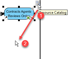
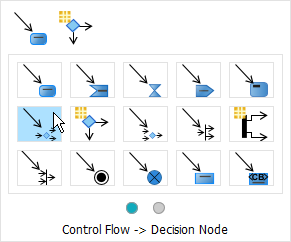
- When creating a decision node, click action that you would like to connect with (Contracts Agents Reviews Order in this example) , click and hold the resource button, then drag to the desire location and release. Choose Control Flow > Decision Node on the popup window. You are allowed drag and move the caption of a decision node.
- Repeat step 11 when creating more decision nodes.
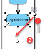
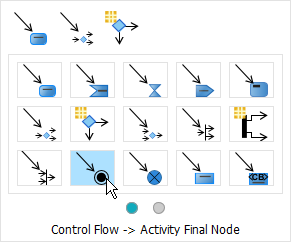
- To create an activity final node, select the final action (Log Shipment in this case) , click the resource button, then drag to the desire position and release. Choose Control Flow > Activity Final Node on the popup window.
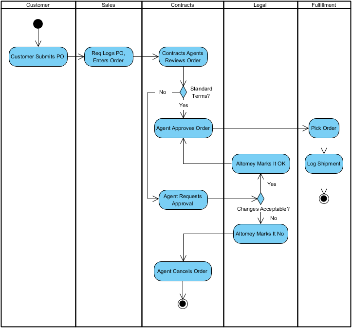
- You will see something similar when finishing your diagram: