
Data Flow Diagrams (DFDs) are essential tools for systems analysts and product managers to visualize how data moves through a system. However, creating detailed, multi-level DFDs manually can be time-consuming and prone to inconsistency. With the advent of AI-assisted modeling tools like the Visual Paradigm (VP) AI Chatbot, this process has become significantly more efficient and intuitive.
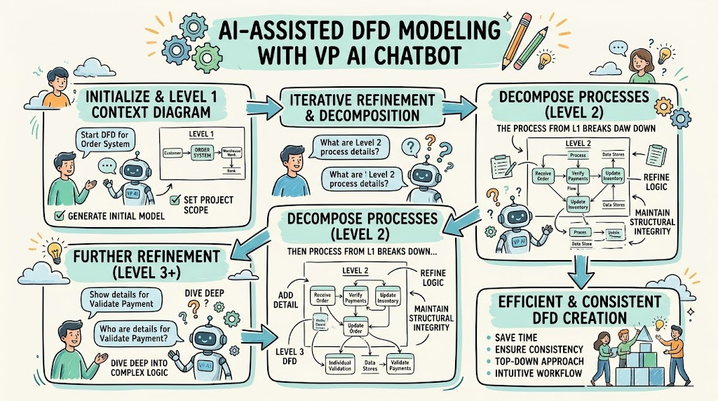
This guide provides a comprehensive tutorial on using the VP AI Chatbot to create Data Flow Diagrams using a top-down decomposition approach. We will walk through the entire lifecycle—from generating an initial Level 1 context diagram to refining specific processes into granular Level 2 and Level 3 diagrams. By leveraging intelligent prompts and iterative refinement questions, you can maintain structural integrity while diving deep into complex system logic.
To begin your visual modeling journey, you need to access the AI assistant within the Visual Paradigm environment.
Open your project in Visual Paradigm.
Locate the AI assistance panel.
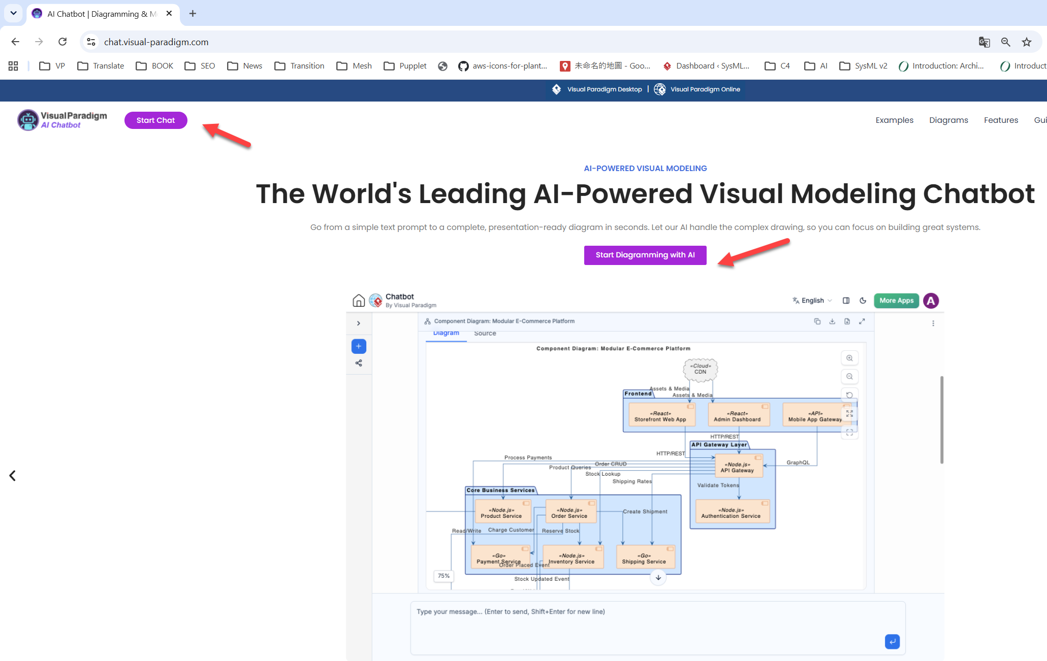
Click on the Start Chat button to initiate the session.
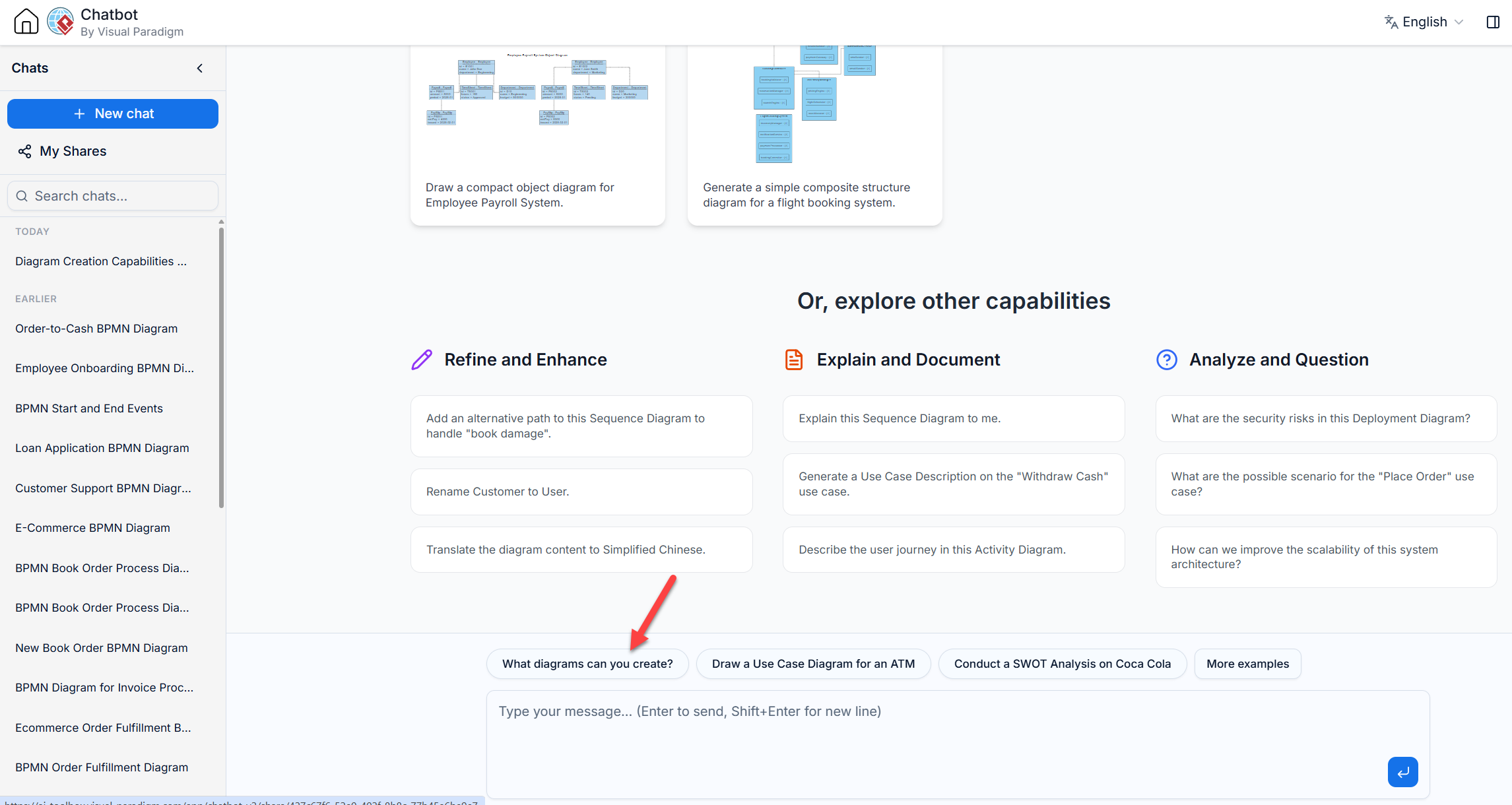
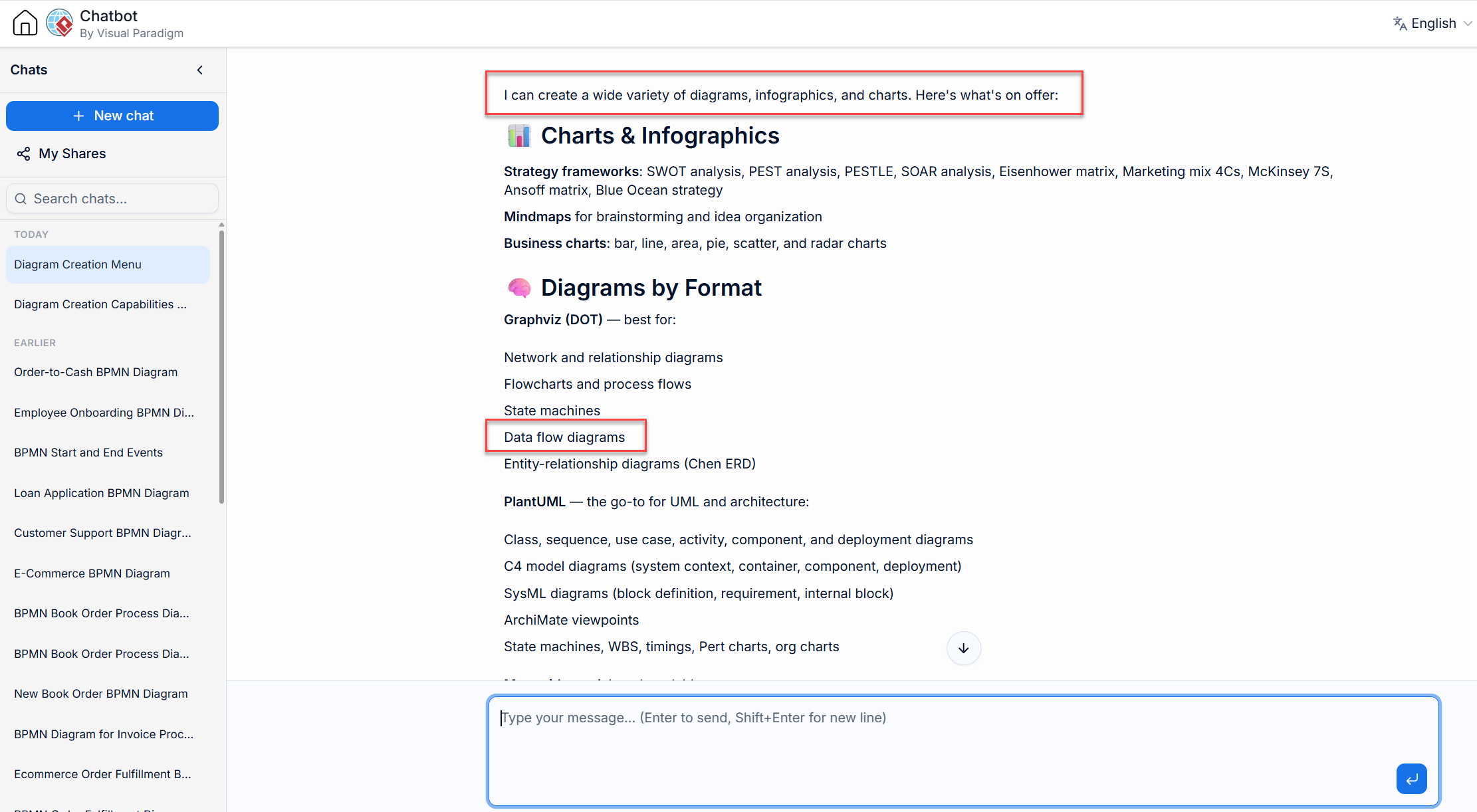
Once the chat interface is active, you are ready to interact with the AI. If you are a new user and unsure of the capabilities, you can start by asking: "What Diagram Can you Create?" The bot will provide a high-level summary of supported diagram types, including UML, BPMN, and DFDs.
The first step in top-down decomposition is establishing the high-level view of the system. This involves defining external entities, major processes, and primary data stores.
Enter a clear, concise prompt describing the system you wish to model. For this tutorial, we will use an Online Order Process System.
Prompt: "Draw A DFD for a Online Order Process system"
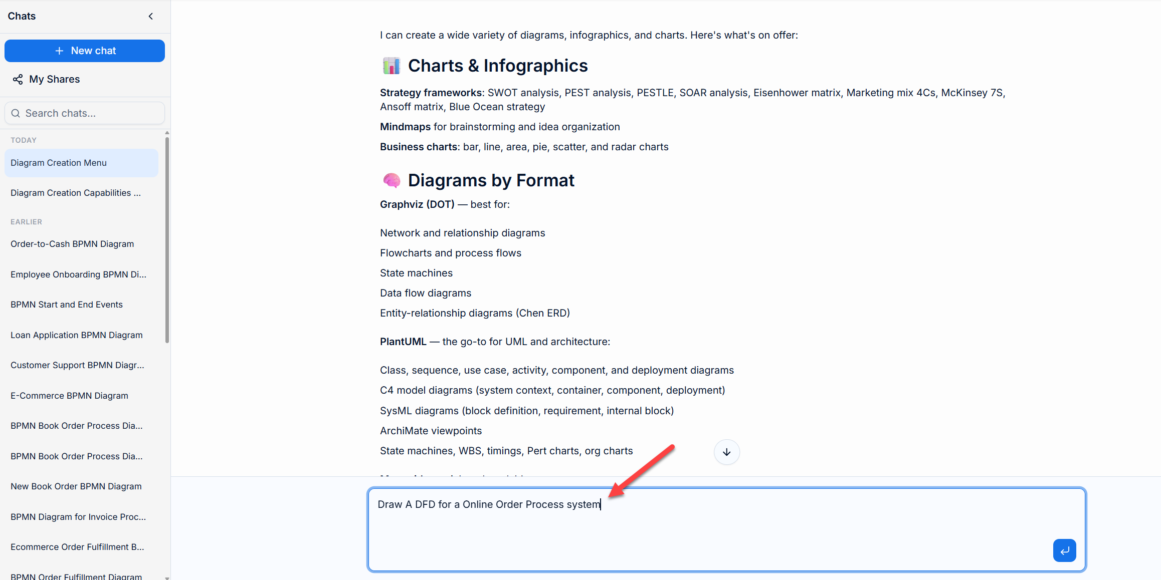
The VP AI Chatbot processes your request, analyzing the requirements to determine the necessary components. It then generates a Level 1 DFD.
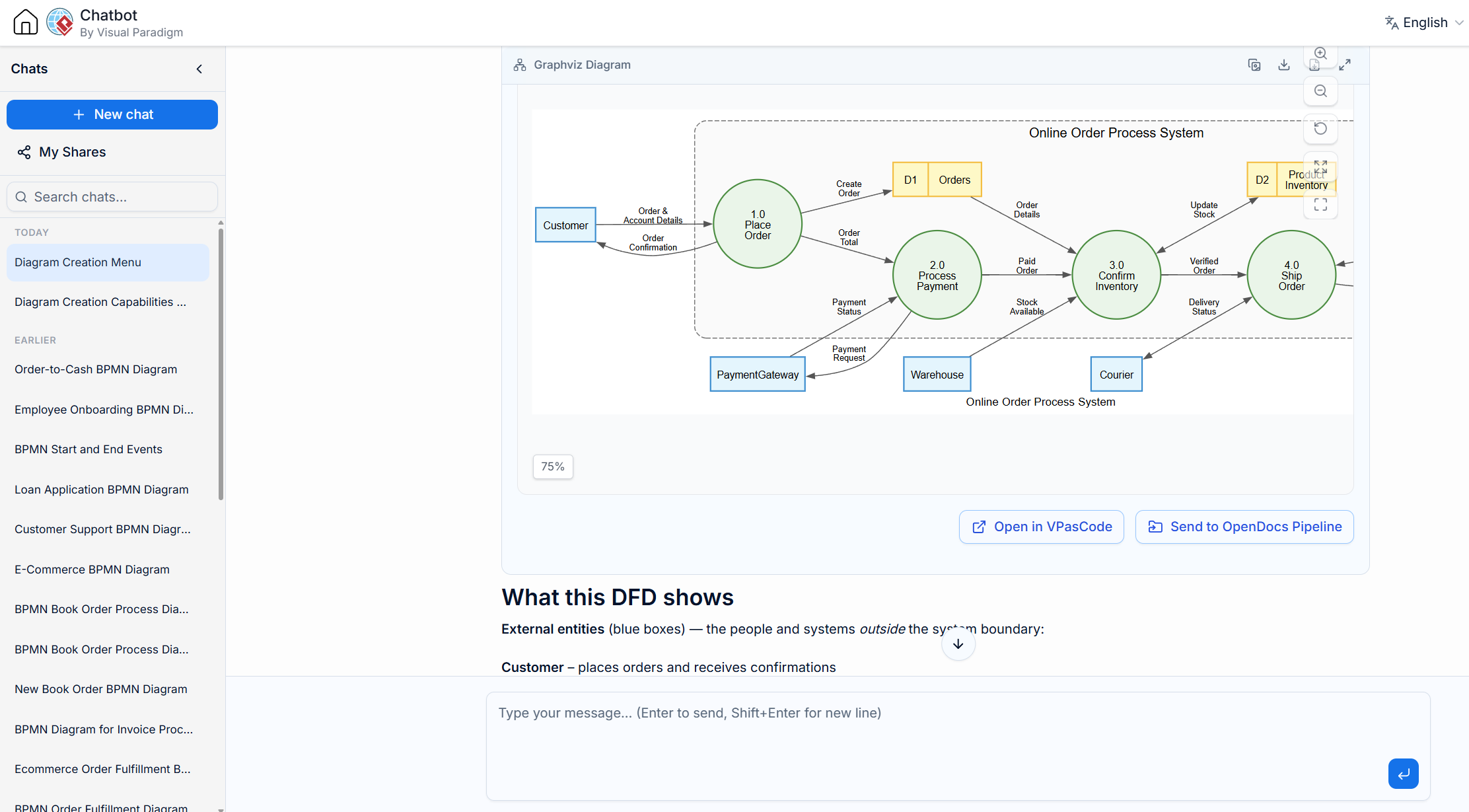
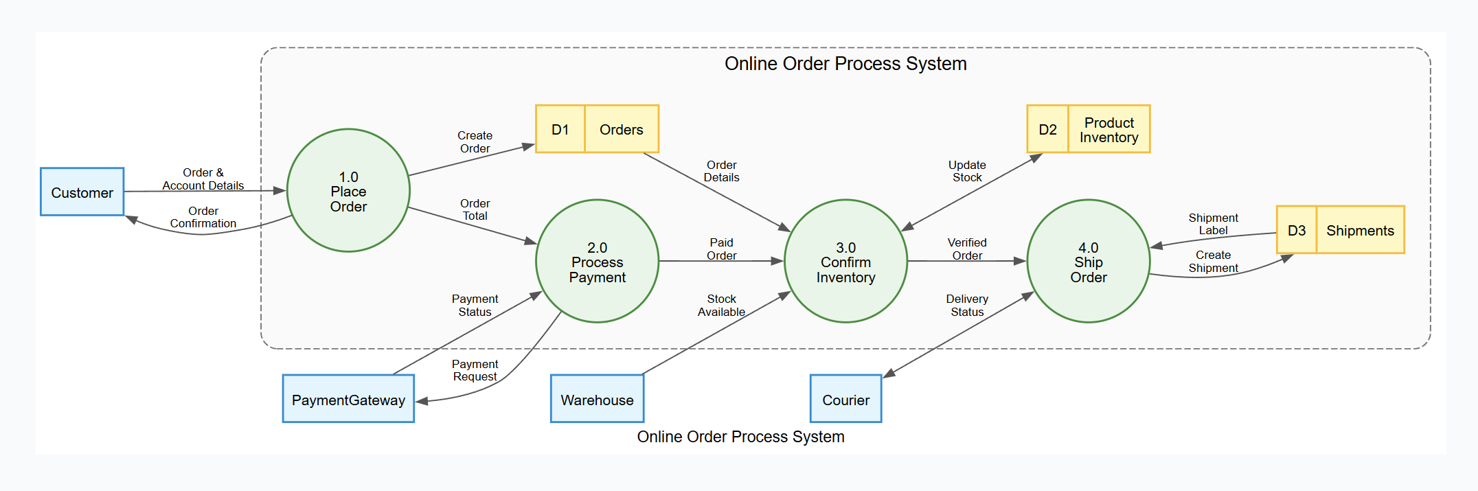
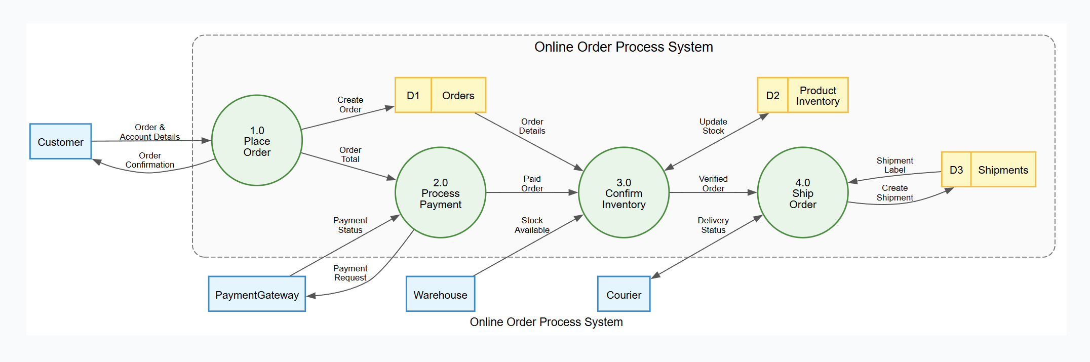
The resulting diagram provides a clear overview of the system boundary and major interactions:
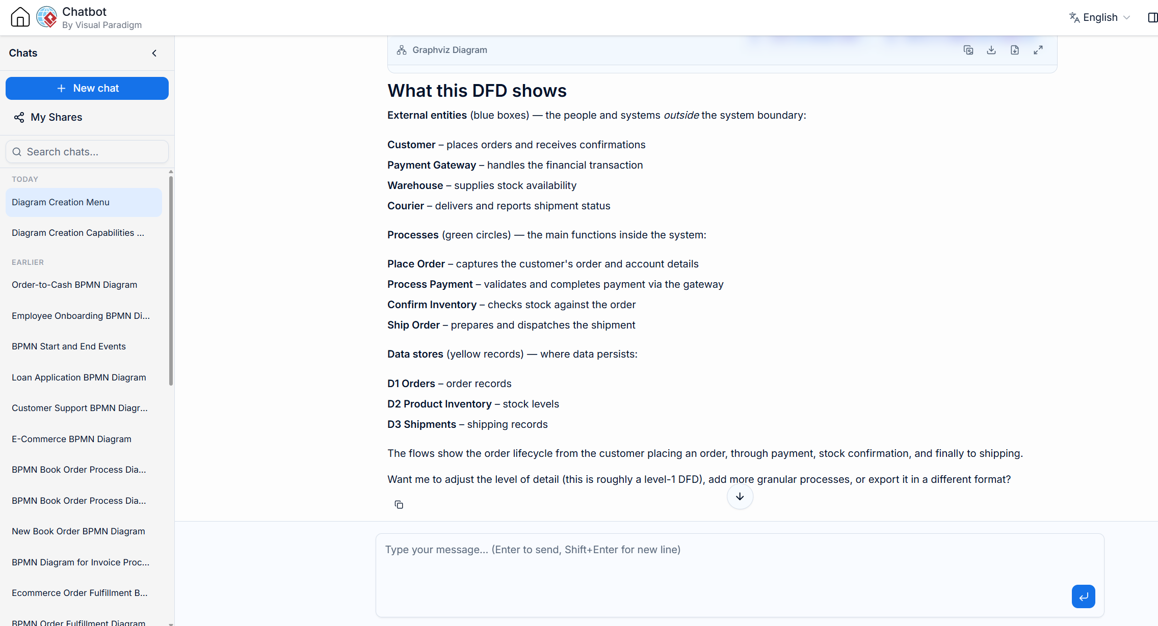
Alongside the visual diagram, the AI provides a textual summary explaining the components:
The AI utilizes Graphviz Dot code to render the diagram. This ensures precision and allows for easy editing if needed. You can view the underlying code by selecting the "Code" tab in the chat interface.
Here is the generated Graphviz code for reference:
digraph DFD {
    // --- GRAPH STYLE & Diagram Title---
    graph [
        rankdir = LR
        splines = true
        overlap = false
        nodesep = 0.5
        ranksep = 0.8
        fontname = "Helvetica,Arial,sans-serif"
        fontsize = 12
        label = "Online Order Process System"
    ]

    // --- NODE STYLES ---
    node [
        fontname = "Helvetica,Arial,sans-serif"
        fontsize = 11
        penwidth = 1.5
    ]

    // External Entities
    node [shape = box, style = "filled", fillcolor = "#E1F5FE", color = "#0288D1"]
    Customer; PaymentGateway; Warehouse; Courier;

    // --- SYSTEM BOUNDARY CONTAINER ---
    subgraph cluster_SystemBoundary {
        label = "Online Order Process System";
        fontname = "Helvetica,Arial,sans-serif"
        fontsize = 14
        color = "#757575"
        style = "dashed,rounded"
        bgcolor = "#FAFAFA"
        margin = 20

        // Processes
        node [shape = circle, style = "filled", fillcolor = "#E8F5E9", color = "#388E3C", fixedsize = true, width = 1.3]
        P1 [label="1.0\nPlace\nOrder"];
        P2 [label="2.0\nProcess\nPayment"];
        P3 [label="3.0\nConfirm\nInventory"];
        P4 [label="4.0\nShip\nOrder"];

        // Data Stores
        node [shape = record, style = "filled", fillcolor = "#FFF9C4", color = "#FBC02D", fixedsize = false]
        OrderDS [label="{ <id> D1 | Orders }"];
        ProductDS [label="{ <id> D2 | Product\nInventory }"];
        ShippingDS [label="{ <id> D3 | Shipments }"];
    }

    // --- EDGE STYLES ---
    edge [
        fontname = "Helvetica,Arial,sans-serif"
        fontsize = 9
        color = "#555555"
        arrowsize = 0.8
    ]

    // --- DATA FLOWS ---
    // Customer interactions
    Customer -> P1 [label="Order &\nAccount Details"];
    P1 -> Customer [label="Order\nConfirmation"];
    P2 -> PaymentGateway [label="Payment\nRequest"];
    PaymentGateway -> P2 [label="Payment\nStatus"];

    // Process to Process
    P1 -> P2 [label="Order\nTotal"];
    P2 -> P3 [label="Paid\nOrder"];
    P3 -> P4 [label="Verified\nOrder"];

    // Process to Data Store
    P1 -> OrderDS [label="Create\nOrder"];                       // write
    P3 -> ProductDS [label="Update\nStock", dir=both];           // read & write
    P4 -> ShippingDS [label="Create\nShipment"];                 // write

    // Data Store to Process
    OrderDS -> P3 [label="Order\nDetails"];                      // read
    ShippingDS -> P4 [label="Shipment\nLabel"];                  // read

    // Courier / Warehouse interactions
    Warehouse -> P3 [label="Stock\nAvailable"];
    Courier -> P4 [label="Delivery\nStatus", dir=both];
}
External Entities (Blue Boxes): Customer, Payment Gateway, Warehouse, and Courier.
Processes (Green Circles):
Place Order
Process Payment
Confirm Inventory
Ship Order
Data Stores (Yellow Records): Orders (D1), Product Inventory (D2), and Shipments (D3).
Top-down decomposition requires breaking down complex processes into smaller, more manageable sub-processes. The VP AI Chatbot facilitates this through intelligent follow-up questions.
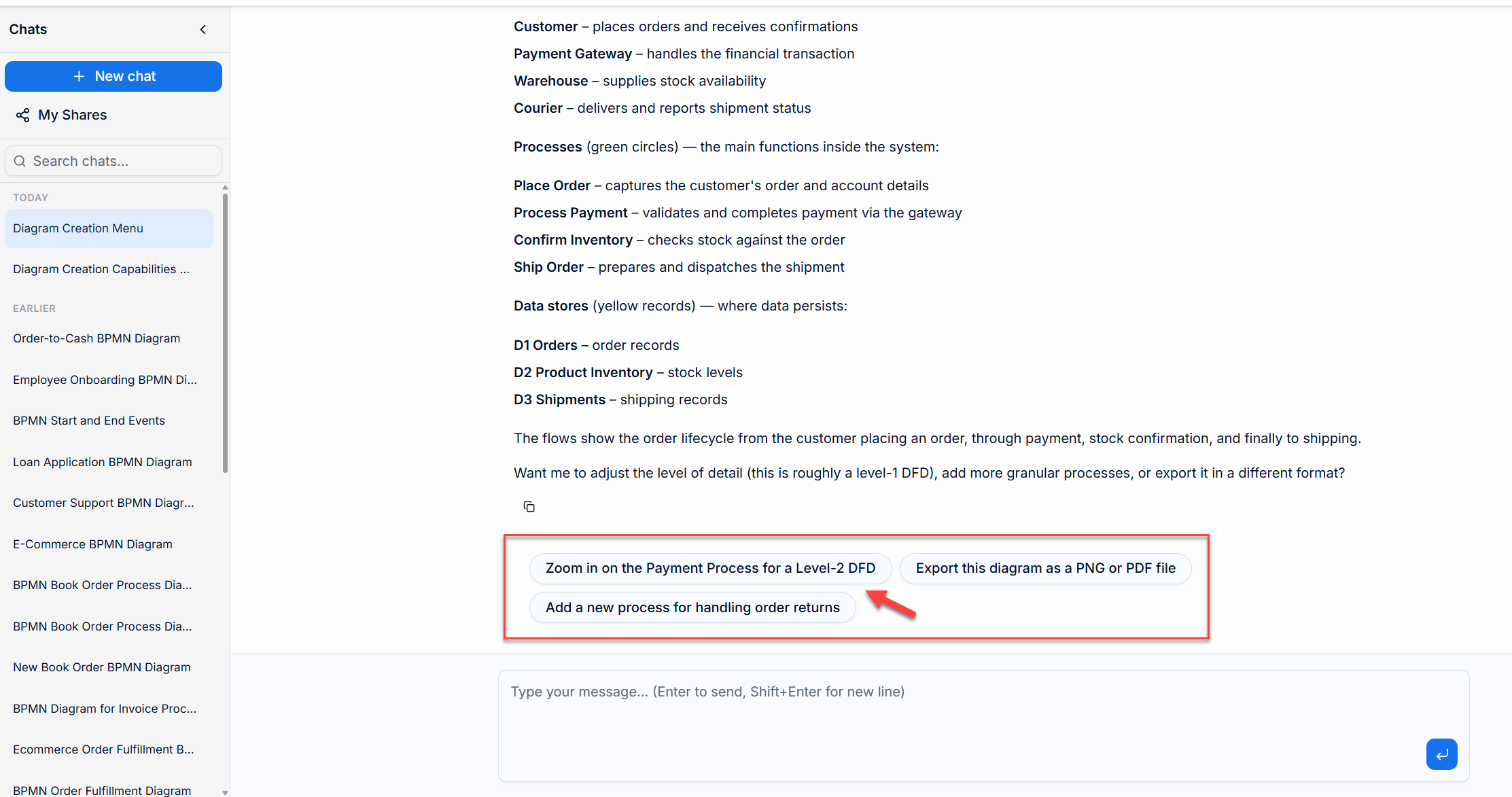
At the bottom of the chat session, the AI suggests extending questions. To refine the payment logic, select:
"Zoom in on the Payment Process for a level 2 DFD"
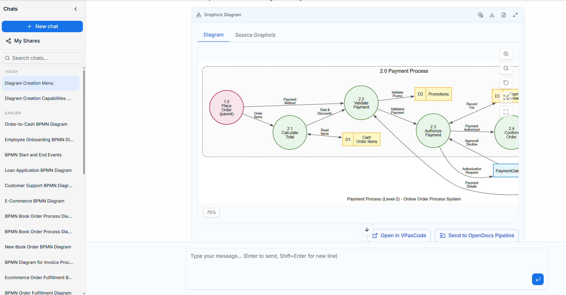
The AI generates a new diagram specifically for Process 2.0: Payment Process.
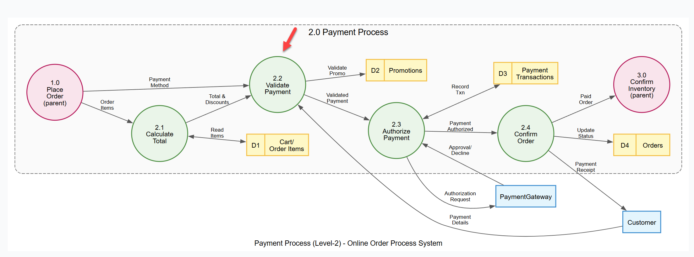
Process 2.0 has been decomposed into four fine-grained sub-processes:
2.1 Calculate Total: Reads cart items and applies promotions.
2.2 Validate Payment: Checks payment methods and promo codes.
2.3 Authorize Payment: Communicates with the external Payment Gateway.
2.4 Confirm Order: Finalizes status and issues receipts.
Key Conventions:
Parent References: Processes 1.0 and 3.0 appear in pink as border references to maintain context.
Local Numbering: Data stores are re-numbered locally (D1–D4) for this sub-diagram.
Bidirectional Flows: Used to reduce clutter where data moves both ways.
Note: You should ideally repeat this refinement process for all other Level 1 processes (Place Order, Confirm Inventory, Ship Order) to complete the system model.
For critical or complex sub-processes, you may need to go even deeper. Let’s refine Process 2.2: Validate Payment further.
In the extending questions section, select:
"Break down the validate Payment sub-process further"
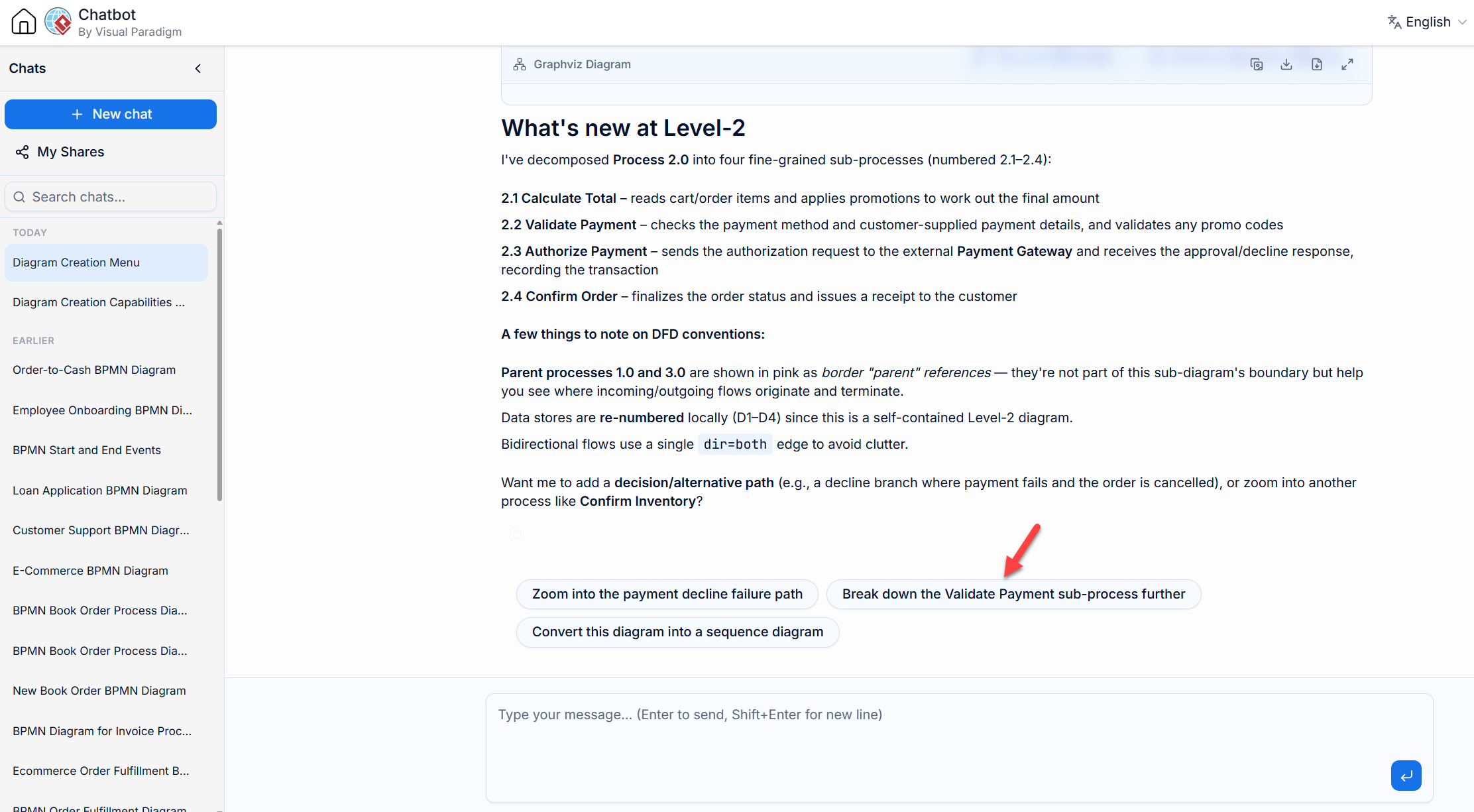
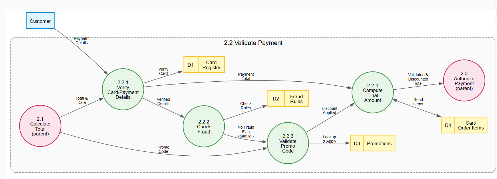
The AI generates a Level 3 DFD for Process 2.2, using the numbering convention 2.2.1, 2.2.2, etc., to indicate hierarchy.
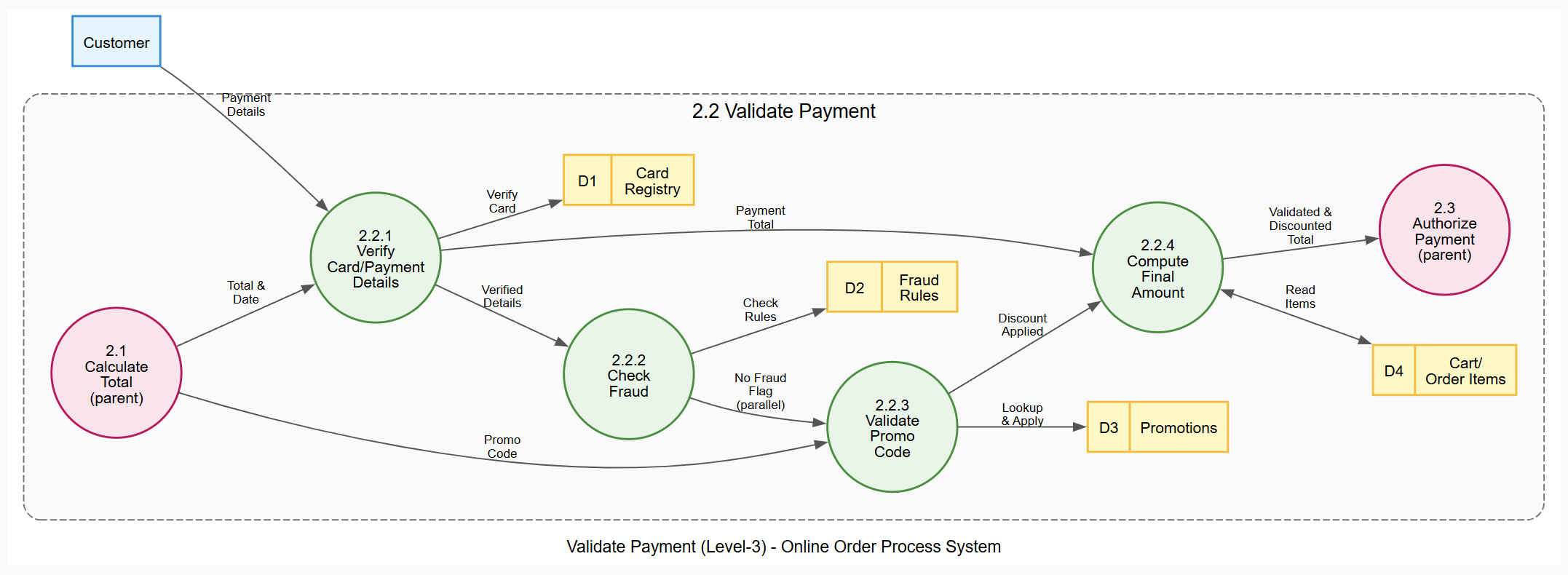
Process 2.2 is decomposed into four leaf-level steps:
2.2.1 Verify Card/Payment Details: Validates card number, expiry, and CVV against the Card Registry.
2.2.2 Check Fraud: Runs details against Fraud Rules for suspicious activity.
2.2.3 Validate Promo Code: Looks up discounts in the Promotions store.
2.2.4 Compute Final Amount: Combines base total with discounts to produce the final validated amount.
Structural Insights:
Steps 2.2.2 (Fraud Check) and 2.2.3 (Promo Validation) can often run in parallel after verification.
Parent processes 2.1 and 2.3 appear in pink to show input/output context.
The Customer entity feeds directly into the verification step.
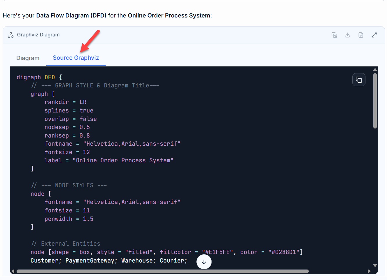
You can view the corresponding Graphviz source code for this level by selecting the Source Tab:
One of the most powerful features of the VP AI Chatbot is its ability to maintain context across complex modeling sessions. You do not need to start a new diagram from scratch every time you want to model a different part of the system. Instead, you can resume existing sessions or branch out into parallel processes, saving time and ensuring consistency across your documentation.
To see this in action without starting from scratch, we have prepared a shared session that includes the entire decomposition process discussed so far (from Level 1 down to the Level 2 Payment Process).
You can access and resume this exact state by clicking the link below:
👉 Resume Shared DFD Session
Once loaded, the chatbot retains the context of the "Online Order Process System." You can immediately proceed to define the next logical step without re-entering the initial system description.
Suppose you have completed the decomposition of the Payment Process (Process 2.0) but now need to define the Confirm Inventory process (Process 3.0) at Level 2. Rather than re-prompting the entire system architecture, simply ask the chatbot to focus on the specific process ID from your original Level 1 DFD.
Enter the following prompt:
"Zoom in on the Confirm Inventory Process for a level 2 DFD"
The AI will recognize the context established in the previous turns and generate the specific sub-diagram for Process 3.0.
Process 3.0 is decomposed into three specialized sub-processes:
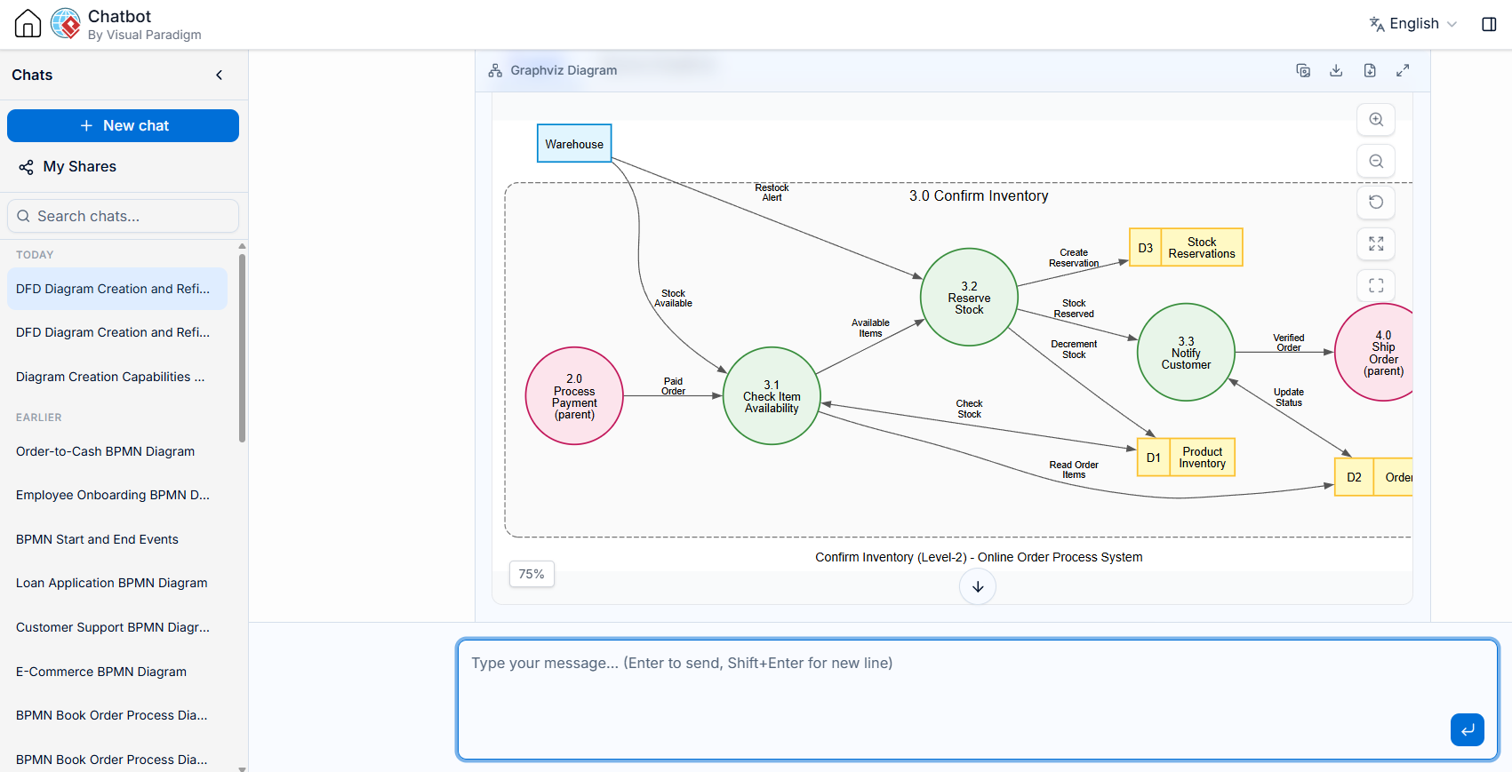
3.1 Check Item Availability: Reads order items and verifies current stock levels against the Product Inventory data store. It also communicates with the Warehouse external entity to confirm physical availability.
3.2 Reserve Stock: Once availability is confirmed, this process decrements the stock in the Product Inventory, creates a record in the Stock Reservations data store, and triggers restock alerts to the Warehouse if levels are low.
3.3 Notify Customer: Updates the order status in the Orders data store to reflect that stock has been reserved, preparing the order for the shipping phase.
Key Structural Elements:
Parent References: Processes 2.0 (Process Payment) and 4.0 (Ship Order) appear in pink as boundary references. This visually demonstrates that the "Paid Order" flows in from Process 2.0, and the "Verified Order" flows out to Process 4.0.
External Entity Interaction: The Warehouse remains outside the system boundary but interacts directly with both the availability check (3.1) and the restock alerting (3.2).
Local Data Stores: Data stores are re-numbered locally for this sub-diagram (D1 Product Inventory, D2 Orders, D3 Stock Reservations) to keep the view clean.
digraph DFD {
// --- GRAPH STYLE & Diagram Title---
graph [
rankdir = LR
splines = true
overlap = false
nodesep = 0.5
ranksep = 0.8
fontname = "Helvetica,Arial,sans-serif"
fontsize = 12
label = "Confirm Inventory (Level-2) - Online Order Process System"
]

// --- NODE STYLES ---
node [
fontname = "Helvetica,Arial,sans-serif"
fontsize = 11
penwidth = 1.5
]

// External Entities (parents from Level-1)
node [shape = box, style = "filled", fillcolor = "#E1F5FE", color = "#0288D1"]
Warehouse;

// --- SYSTEM BOUNDARY CONTAINER ---
subgraph cluster_SystemBoundary {
label = "3.0 Confirm Inventory";
fontname = "Helvetica,Arial,sans-serif"
fontsize = 14
color = "#757575"
style = "dashed,rounded"
bgcolor = "#FAFAFA"
margin = 20

// Sub-processes
node [shape = circle, style = "filled", fillcolor = "#E8F5E9", color = "#388E3C", fixedsize = true, width = 1.3]
P31 [label="3.1\nCheck Item\nAvailability"];
P32 [label="3.2\nReserve\nStock"];
P33 [label="3.3\nNotify\nCustomer"];

// Data Stores
node [shape = record, style = "filled", fillcolor = "#FFF9C4", color = "#FBC02D", fixedsize = false]
ProductDS [label="{ <id> D1 | Product\nInventory }"];
OrderDS [label="{ <id> D2 | Orders }"];
ReservationDS [label="{ <id> D3 | Stock\nReservations }"];

// Parent processes (from Level-1/Level-2)
node [shape = circle, style = "filled", fillcolor = "#FCE4EC", color = "#C2185B", fixedsize = true, width = 1.3]
P2 [label="2.0\nProcess\nPayment\n(parent)"];
P4 [label="4.0\nShip\nOrder\n(parent)"];
}

// --- EDGE STYLES ---
edge [
fontname = "Helvetica,Arial,sans-serif"
fontsize = 9
color = "#555555"
arrowsize = 0.8
]

// --- DATA FLOWS ---
// Parent process input
P2 -> P31 [label="Paid\nOrder"];

// Sub-process chain
P31 -> P32 [label="Available\nItems"];
P32 -> P33 [label="Stock\nReserved"];

// Flows to parent process
P33 -> P4 [label="Verified\nOrder"];

// Data store accesses
P31 -> OrderDS [label="Read Order\nItems"];
P31 -> ProductDS [label="Check\nStock", dir=both];
P32 -> ProductDS [label="Decrement\nStock"];
P32 -> ReservationDS [label="Create\nReservation"];
P33 -> OrderDS [label="Update\nStatus", dir=both];

// Warehouse interaction (external entity)
Warehouse -> P31 [label="Stock\nAvailable"];
Warehouse -> P32 [label="Restock\nAlert"];
}In a real-world scenario, Process 3.1 (Check Item Availability) would likely include a branching path for insufficient stock. If an item is unavailable, the system might split the order into "available now" and "backordered" items, or notify the customer of a delay. The AI can further refine this logic if you ask it to "Add a backorder handling path to Process 3.1."
By leveraging the chatbot's memory via shared sessions, you can seamlessly jump between different branches of your system architecture—moving from Payment to Inventory to Shipping—without losing the thread of your overall design. This iterative, non-linear approach allows you to build complex, comprehensive system models efficiently.
Now that you have mastered the basics of top-down decomposition using the "Confirm Inventory" example, you might want to get your hands dirty and try modeling a different part of the system or a completely new system. However, starting from scratch every time can be time-consuming.
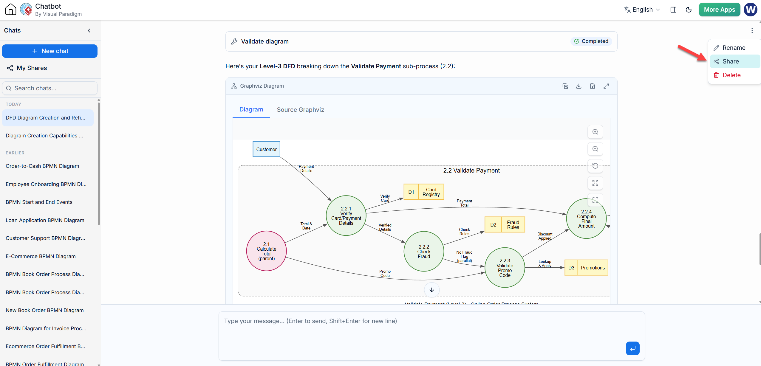
The Visual Paradigm AI Chatbot offers a powerful feature that allows you to resume and extend existing sessions. This means you don't have to re-explain the entire context to the AI. You can pick up exactly where you left off, or even share your progress with team members for collaboration.
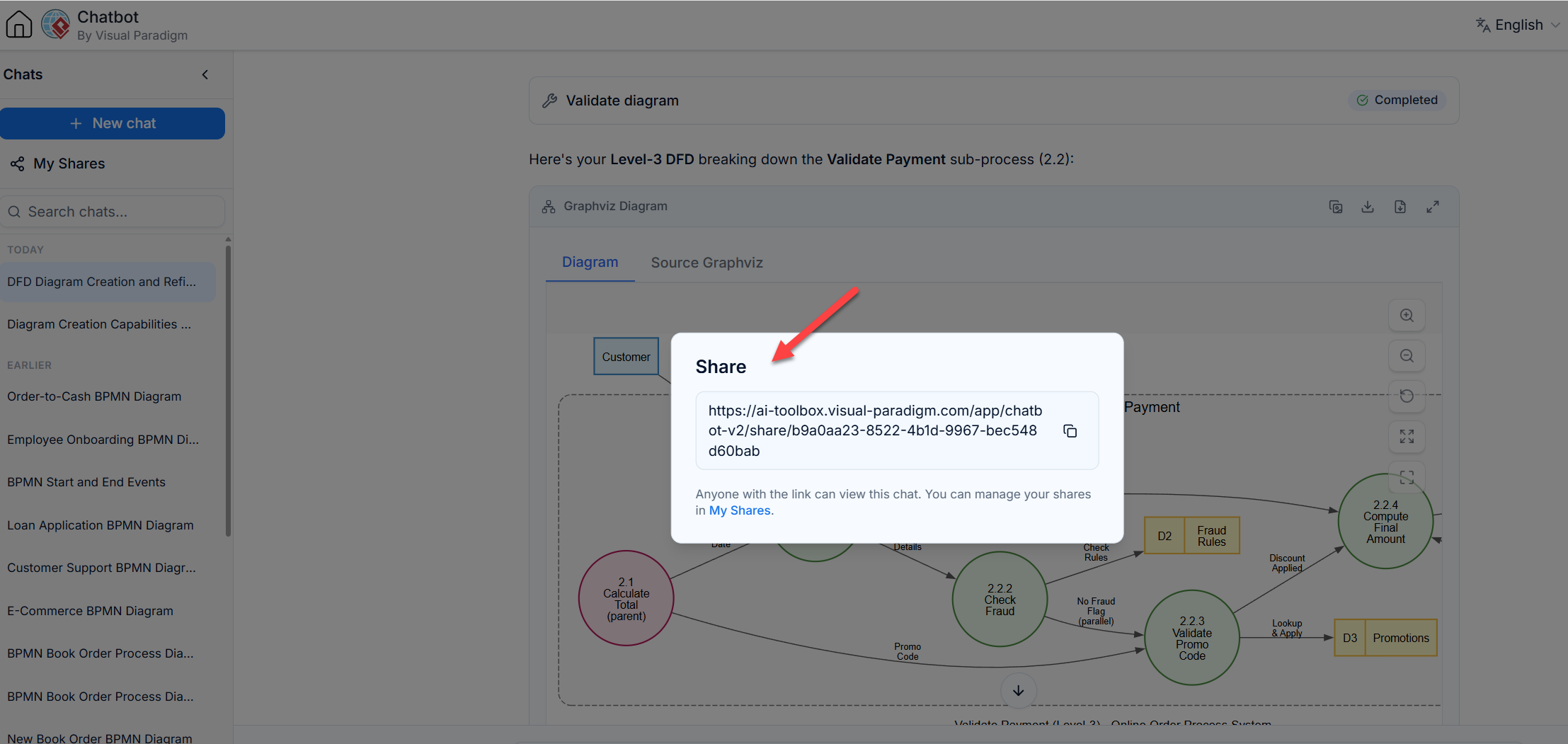
Access Your Shares: Click on the My Share button in the VP AI Chatbot interface. You will see a list of all your previously shared sessions.
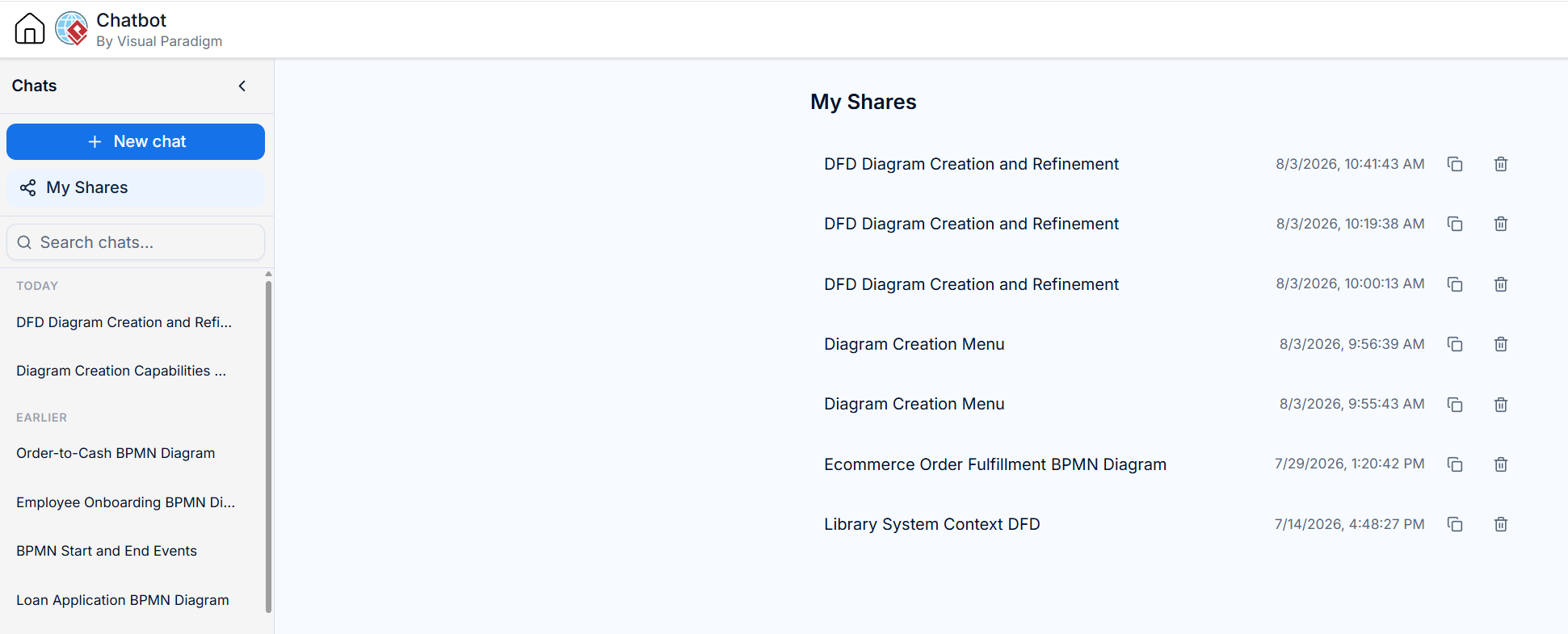
Select a Session: Choose the session you want to continue working on. For this exercise, we will use the "Confirm Inventory" session we just created.
Resume and Extend: Once the session is loaded, the AI retains the full context of your previous DFDs (Level 0, Level 1, and the Level 2 "Confirm Inventory" diagram). You can now immediately ask it to decompose another process, such as "Break down Process 3.1 Check Item Availability into Level 3," without redefining the parent processes.
Efficiency: You save time by not having to re-prompt the initial context.
Consistency: The AI maintains the naming conventions and structural logic established in previous steps.
Collaboration: You can share the session URL with colleagues, allowing them to jump into the exact same context and continue the modeling process or provide feedback.
By leveraging shared sessions, you transform the VP AI Chatbot from a simple diagram generator into a collaborative, persistent modeling assistant that grows with your project.
AI-assisted visual modeling transforms the tedious task of diagramming into a dynamic, interactive conversation. By using the Visual Paradigm AI Chatbot, you can rapidly prototype high-level system architectures and seamlessly drill down into specific functional areas using top-down decomposition.
This approach ensures that your DFDs remain consistent, accurate, and easy to understand at every level of abstraction. Whether you are defining broad system boundaries or detailing specific validation logic, the AI acts as an intelligent partner, handling the syntax and layout so you can focus on the system design itself.

