What's New in ArchiMate 3?

The ArchiMate Specification, an Open Group Standard, is an open and independent modeling language for Enterprise Architecture modeling. This article provides an overview of the ArchiMate 3.0 Specification which is a major update to the ArchiMate 2.1 Specification and was published as an Open Group Standard in June 2016.

Draw ArchiMate with a Certified EA Tool

Visual Paradigm Enterprise Edition is a certified ArchiMate 3 enterprise architecture tool. It supports all ArcihMate 3 vocabulary, notation, syntax, and semantics.

Download Now

Purpose of ArchiMate

  • The ArchiMate language enables Enterprise Architects to describe, analyze, and visualize the relationships among architecture domains in an unambiguous way.
  • Just like an architectural drawing in classical building architecture describes the various aspects of the construction and use of a building.
  • The ArchiMate language offers a common language for describing the construction and operation of business processes, organizational structures, information flows, IT systems, and technical and physical infrastructure.
  • ArchiMate models enable stakeholders to design, assess, and communicate the consequences of decisions and changes within and between these architecture domains.

New Features in ArchiMate 3

New features included in Version 3.0 include new elements for modeling capabilities:

  • The enterprise at a strategic level, such as capability, resource, and outcome.
  • The physical world of materials and equipment.
  • The consistency and structure of the language have been improved, definitions have been aligned with other standards
  • The enhancement in usability in various other ways.

The Origin of ArchiMate Visual Modeling Language

The ArchiMate modeling language provides a uniform representation for diagrams that describe Enterprise Architectures, and offers an integrated approach to describe and visualize the different architecture domains together with their underlying relations and dependencies. The role of the ArchiMate Specification is to provide a graphical language for the representation of Enterprise Architectures which includes:

  • Strategic, transformation
  • Migration planning
  • Motivation and rationale

The design of the ArchiMate language started from a set of relatively generic concepts (objects and relations), which have been specialized for application at the different architectural layers of an Enterprise Architecture.

The Goals of ArchiMate 3

The most important goal for the ArchiMate 3 is that:

  • It has been explicitly designed to be as compact as possible, yet still usable for most Enterprise Architecture modeling tasks.
  • In the interest of simplicity of learning and use, the language has been limited to the concepts that suffice for modeling the proverbial 80% of practical cases.

ArchiMate 3 Enhancements

The new version of the language has been created to respond to a number of requirements:

  • Increasing demand for relating business strategy with business and IT operations
  • Technology innovations that mix IT and the physical world
  • Usage in new domains; e.g., manufacturing, logistics
  • Improved consistency and comprehensibility
  • Improved alignment between Open Group standards, notably with the TOGAF Framework

The key changes in the new ArchiMate 3 specification are provided below.

Two New Layers in ArchiMate 3

The ArchiMate framework has been extended to include strategy and physical layers, as shown in figure below:

ArchiMate 3 2 new layers

The strategy elements include elements for capability, resource, and course of action. The physical elements build upon the Technology Layer and add elements for modeling physical facilities and equipment, distribution networks, and materials.

The Strategy Layer

Elements have been added to support modeling strategy, capability-based planning, and related domains. This supports the increased usage of Enterprise Architecture in supporting strategy execution, and is in line with approaches used in related standards, such as the TOGAF Framework and the Business Motivation Model.

Note that:

Outcome, course of action, capability, and resource are new elements introduced in the ArchiMate 3.0 Specification.

The Strategy Layer

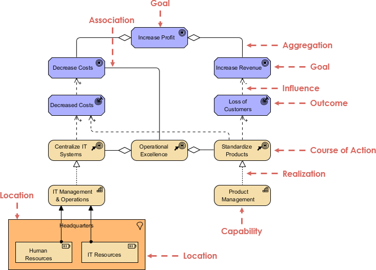
From the figure, you can see that:

  • Increase Profit is a goal that can be decomposed into a number of other goals: Decrease Costs and Increase Revenue.
  • The former is related to the Operational Excellence strategy of the company, modeled as a course of action.
  • This is decomposed into two other courses of action: Centralize IT Systems and Standardize Products.
  • The two outcomes: Decreased Costs and Loss of Customers influence the goals in positive and negative ways.
  • This shows an important difference between goals and outcomes: not all outcomes lead to the intended results.

Outcome Realization by Capabilities

The courses of action are realized by a number of capabilities:

  • IT Management & Operations
    • Appropriate resources Human Resources and IT Resources are assigned to the former.
    • The model fragment also shows that these resources are located in the Headquarters of the organization, in line with the Centralize IT Systems course of action
  • Product Management

The Physical Layer

The Technology Layer has been extended with elements for modeling the physical world; for example:

  • Manufacturing
  • Logistics
  • other physical environments

Note that:

All the elements shown in the example below, except for Path, are new in the ArchiMate 3.0 Specification, and Path has been renamed from Communication Path and its meaning extended to allow it to integrate with physical elements.

The Physical Layer

By reading the flow surrounded by dotted line in the figure above, you can see that an Assembly Line, modeled as equipment, and installed at a facility Manufacturing Plant, makes use of materials Pre-Assembled Circuit Board, Internal Antenna, and Plastic Case to produce material Vehicle Telematics Appliance.

The Physical Layer 2

By studying the elements surround by dotted line in the figure above, you can see that the appliance, initially located at the Manufacturing Plant facility, is subsequently transported to the facilities National Distribution Center and Local Distribution Center, making use of the distribution networks Overseas Shipping and Local Trucking. These distribution networks together realize the path Intermodal Freight.

Improved Usability and Consistency

A number of changes have been made to the language to improve its usability and consistency. These are summarized below:

Generic Metamodel

An upper-level generic metamodel has been introduced to document the full structure of behavior and structure elements of the ArchiMate language presenting in the metamodel fragment as shown in the figure below. It defines these elements in a generic, layer-independent way.

Metamodel

Note That:

  • This generic metamodel fragment consists of two main types of elements: structure ("nouns") and behavior elements ("verbs").
  • The white boxes are abstract metamodel elements; i.e., these are not instantiated in models but only serve to structure the metamodel.
  • The gray boxes can be used to model the Enterprise Architecture at a strategic level

Composite Elements

In ArchiMate 3, grouping and location are generic composite elements which has been updated. Composite elements can themselves aggregate or compose other composite elements.

Grouping

The grouping element aggregates or composes concepts that belong together based on some common characteristic.

  • The element is no longer classified as a relationship, it is now a composite element.
  • A grouping now has an aggregation or composition relationship with its contents, making it much more useful.
  • It is also permissible to draw relationships from or to a grouping.

For Example, in the model below, the Grouping element is used to aggregate a conglomerate of two processes and an object that together realize a service (both with nesting and explicitly drawn aggregation relationships).

Grouping
Location

A location is a place or position where structure elements can be located or behavior can be performed. The location element is used to model the places where (active and passive) structure elements such as business actors, application components, and devices are located.

  • This element has been moved from the Business Layer to the generic metamodel and defined as a composite element.
  • Improvements in the use of nesting as a notation allow a better representation of related items in modeling
Location

Changed the Notation for the Representation and Contract Elements

The notation of representation and contract has been changed to differentiate these from deliverable and business object, respectively.

Node Description Changed Graphic Notation

Representation

  • A representation represents a perceptible form of the information carried by a business object.
  • For example, in terms of medium (electronic, paper, audio, etc.) or format (HTML, ASCII, PDF, RTF, etc.).
  • A single business object can have a number of different representations.
  • Also, a single representation can realize one or more specific business objects.
Representation

Example

Representation example

Contract

  • A contract represents a formal or informal specification of an agreement between a provider and a consumer
  • It specifies the rights and obligations associated with a product and establishes functional and non-functional parameters for interaction.
Contract

Deliverable

  • A deliverable represents a precisely-defined outcome of a work package.
  • Work packages produce deliverables. These may be results of any kind
  • For example: reports, papers, services, software, physical products, etc., or intangible results such as organizational change.
Deliverable

Business Object

  • A business object represents a concept used within a particular business domain
  • Business objects are passive in the sense that they do not trigger or perform processes.
  • A business object could be used to represent information assets that are relevant from a business point of view
  • It can be realized by data objects.
Business Object

Optional Notation to Denote the Layer of an Element

An optional notation has been introduced to explicitly denote the layer of an element. A letter 'M', 'S', 'B', 'A', 'T', 'P', or 'I' in the top-left corner of an element can be used to denote a Motivation, Strategy, Business, Application, Technology, Physical, or Implementation & Migration element, respectively.

Relationships

Relationship Notation Updated

Updated Relationship Example

Object Flow

  • Relationships to other relationships are now allowed in some cases;
  • e.g., to associate objects with flows or aggregate relationships within groupings or plateaus similar object flow in UML
Relationships

Used by

  • The 'used by' relationship has had its name changed to 'serving', to better reflect its direction with an active verb: a service serves a user.
  • The meaning of the relationship has not been altered. The 'used by' designation is still allowed but deprecated, and will be removed in a future version of the standard.
  • The notation of the influence relationship has been changed for consistency with the other dependency relationships (access and serving).
Use By

Directional Notation

  • A directional notation has been introduced for the assignment relationship by replacing the black circle at the target end by an arrow.
Directional Notation

Influence relationship

  • The notation of the influence relationship has been changed for consistency with the other dependency relationships (access and serving).
Influence Relationship

Junction

  • A junction is no longer classified as a relationship, but as a relationship connector, A junction is now explicitly either an 'or' junction, or a general 'and' junction.
Junction

Viewpoint Mechanism in ArchiMate 3

A viewpoint in ArchiMate is a selection of a relevant subset of the ArchiMate concepts (and their relationships) and the representation of that part of an architecture that is expressed in different diagrams. A set of such viewpoints was developed based on practical experience. The following are examples of stakeholders and concerns as a basis for the specification of viewpoints:

  • End user: what are the consequences for his work and workplace?
  • Architect: What is the consequence for the maintainability of a system, with respect to corrective, preventive, and adaptive maintenance?
  • Upper-level management: How can we ensure our policies are followed in the development and operation of processes and systems? What is the impact of decisions (on personnel, finance, ICT, etc.)?
  • Operational manager: Responsible for exploitation or maintenance: For example, what new technologies are there to prepare for? Is there a need to adapt maintenance processes? What is the impact of changes to existing applications? How secure are my systems?
  • Project manager: Responsible for the development of new applications: What are the relevant domains and their relationships? What is the dependence of business processes on the applications to be built? What is their expected performance?
  • Developer: What are the modifications with respect to the current situation that need to be done?

Previous versions of the standard included an extensive list of viewpoints within the normative body of the standard, and the ability to define viewpoints to fit a particular situation. In Version 3.0, the description of the viewpoint mechanism has been improved, and the list of viewpoints has been placed in an informative appendix to make it clear that these are example viewpoints.

Want to create ArchiMate diagrams?

Try Visual Paradigm Enterprise Edition, an enterprise architecture software that features a powerful ArchiMate drawing tool, ArchiMate viewpoint management tool and TOGAF Guide-through Process.

Try it Free

Turn every software project into a successful one.

We use cookies to offer you a better experience. By visiting our website, you agree to the use of cookies as described in our Cookie Policy.

OK