In the complex world of software engineering, the ability to visualize, specify, and document system architecture is paramount. For over two decades, the Unified Modeling Language (UML) has served as the de facto industry standard for creating visual blueprints of software-intensive systems. Originally conceived in the mid-1990s by the "Three Amigos" — Grady Booch, James Rumbaugh, and Ivar Jacobson — UML was adopted by the Object Management Group (OMG) in 1997 and has since evolved through multiple iterations.
Today, the latest formal version, UML 2.5.1 (adopted in December 2017), represents the culmination of nearly twenty-five years of refinement. Unlike earlier major releases that introduced groundbreaking new diagram types, UML 2.5.1 is a testament to the principle that maturity in a standard often means simplification rather than expansion. This case study examines the structural, semantic, and architectural refinements that define UML 2.5.1, explores its canonical set of 14 diagram types, and considers its continued relevance in modern software development practices — from Agile workflows to microservices architectures and AI-driven diagram analysis.
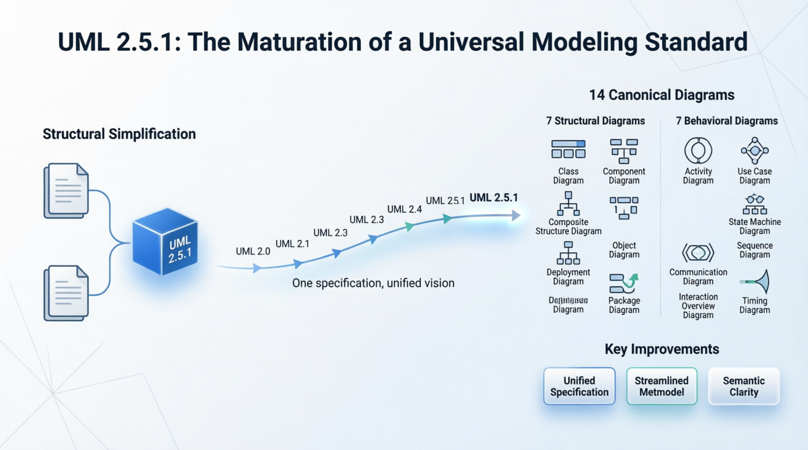
The Unified Modeling Language has undergone several major transformations since its inception. The most significant leap occurred with UML 2.0, which nearly doubled the number of diagram types and introduced a more rigorous metamodel. Subsequent versions — 2.1, 2.2, 2.3, 2.4, 2.5, and finally 2.5.1 — have been iterative refinements rather than revolutionary overhauls.
Because UML is a mature and highly stable standard, newer minor releases like UML 2.5 and UML 2.5.1 do not introduce brand-new diagram types. Instead, they focus on radical document simplification, architectural cleanup, and fixing severe metamodel ambiguities. The result is a specification that is more accessible to tool vendors, more consistent for engineers, and more reliable for enterprise adoption.
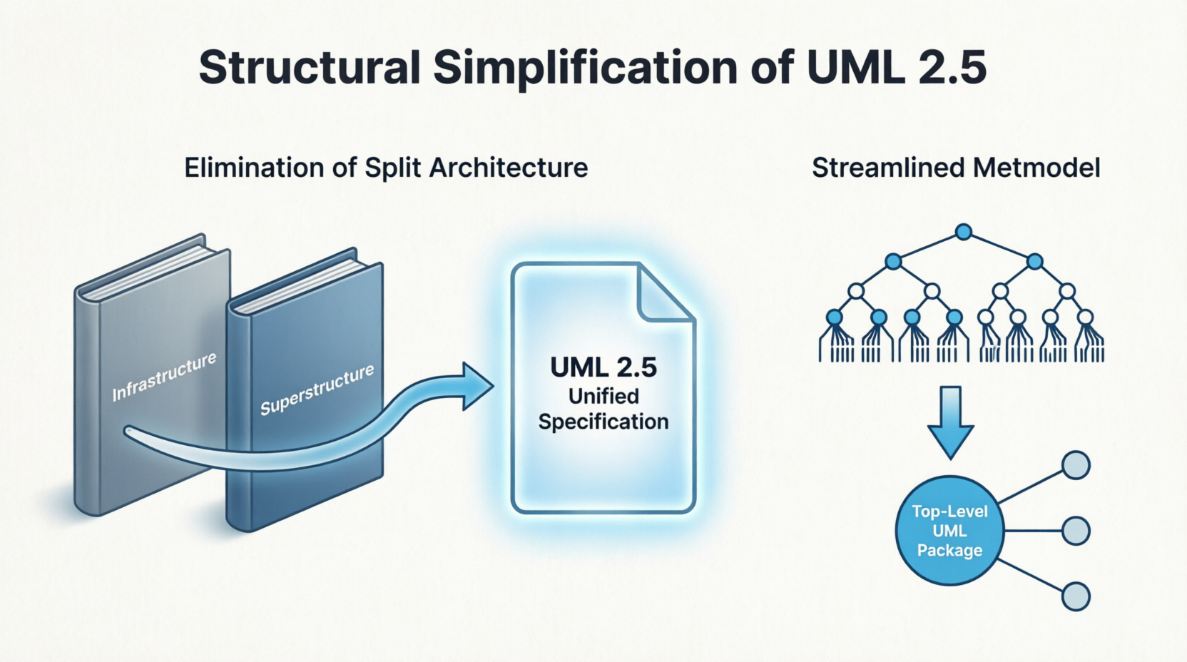
Prior to version 2.5, the UML specification was notoriously split into two separate, distinct documents: the Infrastructure (which defined the core metamodel foundation) and the Superstructure (which defined the notation and semantics for diagrams). This bifurcation created significant challenges for tool vendors and practitioners, who had to cross-reference two massive documents to understand a single modeling concept.
The UML 2.5 standard merged these two documents into a single, cohesive volume. This consolidation made the specification vastly easier to interpret and implement, reducing the cognitive overhead for anyone building UML-compliant tools or studying the standard in depth.
The package structure of the UML metamodel was significantly compressed in the 2.5 release. All secondary sub-packages are now directly imported into a single, top-level UML package, which minimizes nested definitions and reduces unnecessary indirection. This architectural cleanup reflects a broader philosophy: a mature standard should become simpler over time, not more complex.
The UML 2.5.1 text was thoroughly rewritten to remove hundreds of minor internal contradictions, specifically around the exact visibility rules for packaged elements and inheritance properties. These clarifications were essential for tool vendors, who had previously been forced to make subjective interpretations of ambiguous specification language. By resolving these contradictions, OMG ensured that different UML tools would produce more consistent results.
One of the most philosophically significant changes in UML 2.5 was the formal elimination of a strict, standalone definition for "Object Diagrams." In the latest specification, object configurations are classified and treated simply as "Instance Specifications" mapped out within standard Class Diagrams. This reclassification reflects the reality that object diagrams were always conceptually a subset of class diagrams — they merely showed instances rather than types. By folding them into the class diagram family, the standard reduces redundancy while preserving full expressive power.
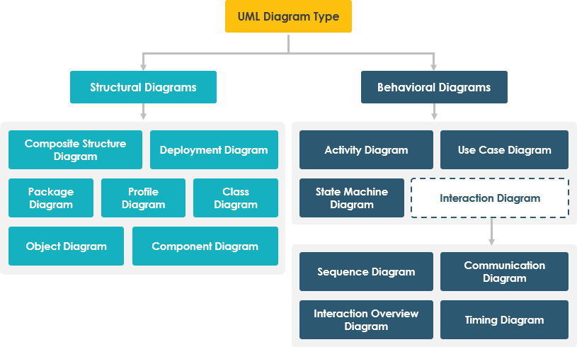
While the 14 canonical diagram types were fundamentally established in the major UML 2.0 shift, the latest standard solidifies and maintains this taxonomy. The diagrams are split into two primary categories: Structural Diagrams (depicting the static architecture of a system) and Behavioral Diagrams (depicting the dynamic interactions and processes within a system).
| Diagram Type | Primary Purpose |
|---|---|
| Class Diagram | Shows the static structure of a system through classes, interfaces, attributes, operations, and relationships |
| Component Diagram | Illustrates how a software system is divided into components and their dependencies |
| Composite Structure Diagram | Depicts the internal structure of a classifier, including parts, ports, and connectors |
| Deployment Diagram | Maps software artifacts onto hardware nodes and execution environments |
| Object Diagram | Shows instance-level snapshots of a system at a specific point in time |
| Package Diagram | Organizes UML elements into packages and shows dependencies between them |
| Profile Diagram | Extends UML with custom stereotypes, tagged values, and constraints |
| Diagram Type | Primary Purpose |
|---|---|
| Activity Diagram | Models workflows, business processes, and concurrent activities |
| Use Case Diagram | Captures functional requirements through actors and their interactions with the system |
| State Machine Diagram | Describes the discrete states of an object and the transitions between them |
| Sequence Diagram | Shows object interactions arranged in time sequence |
| Communication Diagram | Emphasizes the structural organization of objects that send and receive messages |
| Interaction Overview Diagram | Provides a high-level overview of control flow using interaction fragments |
| Timing Diagram | Focuses on timing constraints and condition changes along a linear time axis |
This taxonomy provides comprehensive coverage of virtually every aspect of software system design, from high-level architectural planning to detailed runtime behavior specification.
Despite the rise of Agile methodologies and lighter-weight documentation approaches, UML remains a vital tool in modern software engineering. Recent research confirms that UML is widely applied in industry contexts including:
Even within Agile environments, UML offers a lightweight, logical framework. Simplified class diagrams represent conceptual structures, while use case diagrams capture high-level interactions — providing just enough structure to support iterative development without imposing excessive documentation overhead.
The UML 2.5.1 standard is supported by a rich ecosystem of professional modeling tools, including:
Despite its maturity, UML faces ongoing challenges:
UML 2.5.1 stands as a landmark achievement in the standardization of software modeling. Rather than chasing novelty, this version of the standard embraces the wisdom that a truly mature specification should prioritize clarity, consistency, and usability over feature expansion. The elimination of the split Infrastructure/Superstructure architecture, the streamlining of the metamodel, and the resolution of semantic ambiguities collectively represent a significant maturation of the language.
The 14 canonical diagram types — seven structural and seven behavioral — provide a comprehensive toolkit for modeling virtually any software system, from simple web applications to complex distributed architectures. Whether used for forward design, reverse engineering, documentation, or communication with stakeholders, UML continues to fulfill its original promise: providing a universal visual language for software engineering.
As the software industry evolves with new paradigms — including AI-driven development, cloud-native architectures, and model-driven engineering — UML 2.5.1 remains a stable, reliable foundation. Its continued relevance is evidenced not only by its widespread adoption in industry but also by its integration into modern AI research, where deep learning models are being trained to understand, classify, and even generate UML diagrams automatically.
For organizations and practitioners, UML 2.5.1 offers a compelling proposition: a standardized, well-documented, and thoroughly refined modeling language that can scale from small Agile teams to large enterprise initiatives. In an era of increasing software complexity, the clarity that UML provides is more valuable than ever.