In today's rapidly evolving software landscape, the ability to visualize, communicate, and validate complex system designs before writing a single line of code has become a critical competitive advantage. Visual modeling serves as the bridge between abstract business requirements and concrete technical implementations, enabling teams to align stakeholders, reduce ambiguity, and accelerate delivery. As systems grow in complexity and development cycles shorten, traditional modeling approaches face new challenges—requiring tools that not only support industry standards like UML but also integrate intelligent automation to keep pace with modern development demands.
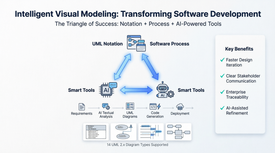
This case study explores how visual modeling principles, when combined with robust process frameworks and AI-enhanced tooling, create a powerful foundation for successful software engineering. We examine the fundamental concepts of abstraction and modeling, the essential "Triangle of Success" framework, and how Visual Paradigm's integrated ecosystem—now augmented with Generative AI—addresses real-world challenges faced by enterprise development teams. Whether you are architecting a new microservices platform, modernizing legacy systems, or managing agile product backlogs, understanding how to leverage intelligent visual modeling can transform your approach to software design and delivery.
Visual Modeling is a way of thinking about problems using models organized around real-world ideas. Models are useful for understanding problems, communicating with everyone involved with the project (customers, domain experts, analysts, designers, etc.), modeling enterprises, preparing documentation, and designing programs and databases. Modeling promotes a better understanding of requirements, cleaner designs, and more maintainable systems.
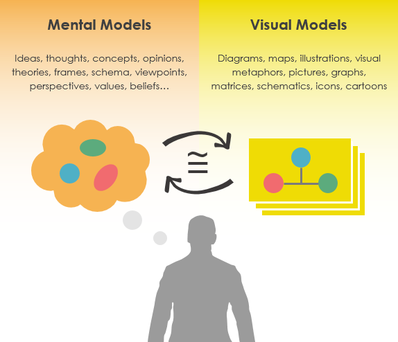
Models are abstractions that portray the essentials of a complex problem or structure by filtering out nonessential details, thus making the problem easier to understand.
Abstraction is a fundamental human capability that permits us to deal with complexity. Engineers, artists, and craftsmen have built models for thousands of years to try out designs before executing them. Development of software systems should be no exception.
Modeling is a proven & well-accepted engineering technique. In building architecture, we develop architectural models of houses & high rises to help visualize the final products. In Unified Modeling Language (UML), a model may be structural, emphasizing the organization of the system or it may be behavioral, emphasizing the dynamics of the system. A model is a simplification of reality, providing blueprints of a system. UML, in specific:
Permits you to specify the structure or behavior of a system.
Helps you visualize a system.
Provides a template that guides you in constructing a system.
Helps to understand complex system part by part.
Document the decisions that you have made.
We build a model so that we can better understand the system we are developing. A model may encompass an overview of the system under consideration, as well as detailed planning for system design, implementation, and testing.
To build complex systems, the developer must abstract different views of the system, build models using precise notations, verify that the models satisfy the requirements of the system, and gradually add detail to transform the models into an implementation.
Different Level of Complexity
We build models of complex systems because we cannot comprehend such systems in their entirety. There are limits to the human capacity to understand complexity. This concept may be seen in the world of architecture.
If you want to build a shed in your backyard, you can just start building;
If you want to build a new house, you probably need a blueprint;
If you are building a skyscraper, you definitely need a blueprint.

The same is true in the world of software. Staring at lines of source code or even analyzing forms in Visual Basic does little to provide the programmer with a global view of a development project. Constructing a model allows the designer to focus on the big picture of how a project's components interact, without having to get bogged down in the specific details of each component.
Increasing complexity, resulting from a highly competitive and ever-changing business environment, offers unique challenges to system developers. Models help us organize, visualize, understand, and create complex things. They are used to help us meet the challenges of developing software today and in the future.
If we are familiar with UML, but if we don't know how to use it by applying a process properly, we will probably fail. We may have a great process or methodology, but if we can't communicate the process using an easy-to-understand notation, we will probably fail. And lastly, if we cannot document the artifacts of our work by using an effective tool, we will probably fail eventually.
Thus, we need all three facets of visual modeling:
notation,
process, and
tool.
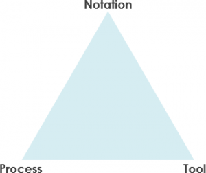
Notation plays an important part in any model – it is the glue that holds the process together. The notation has three roles:
It serves as the visual language for communicating decisions that are not obvious or cannot be inferred from the code itself.
It provides semantics that is rich enough to capture all-important strategic and tactical decisions.
It offers a form concrete enough for humans to reason and for tools to manipulate.
The Unified Modeling Language (UML) provides a very robust notation, which grows from analysis into the design. Certain elements of the notation (for example, classes, associations, aggregations, inheritance) are introduced during analysis. Other elements of the notation (for example, containment implementation indicators and properties) are introduced during design.
A Process Model describes the sequence of phases for the entire lifetime of a product. Therefore it is sometimes also called the Software Development Life Cycle (SDLC) which is a structure imposed on the development of the targeted system.
A software process is represented as a set of work phases that is applied to design and build a software product such as the waterfall process, Spiral, V-model, agile & Scrum process, LeSS, XP, Kanban and etc.
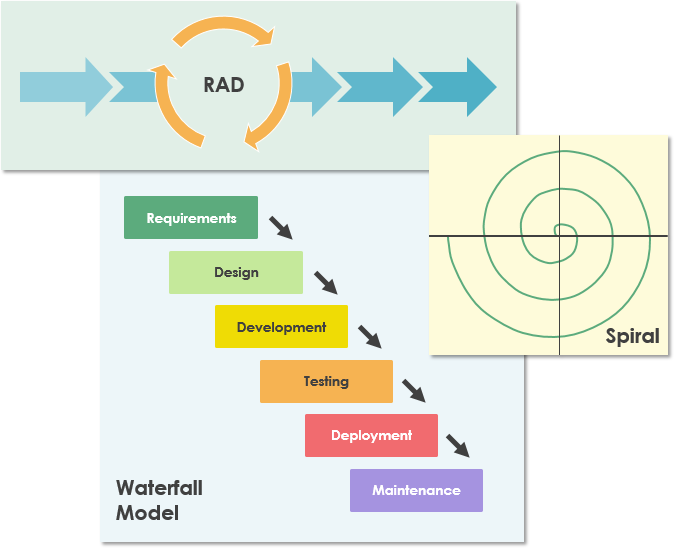
There is no ideal software process, and many organizations have developed their own approaches to software development. Software development processes should make maximum use of the capabilities of the people in an organization and the specific characteristics of the systems that are being developed.
Any software development method is best supported by a tool. There are many tools on the market today. From simple drawing tools to sophisticated one-stop-shop development platforms such as Visual Paradigm. Visual Paradigm is designed to provide the software developer with a complete set of visual modeling tools for the development of robust, efficient solutions faster, better and cheaper!
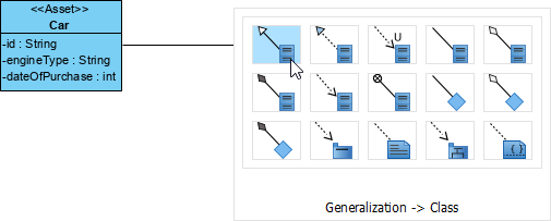
Create a connected shape instantly through the Resource Catalog feature. It's simply a drag-and-drop to create a shape.
Visual Paradigm supports a wide range of modeling standards and languages – UML, BPMN, ArchiMate, DFD, ERD, SoaML, SysML, CMMN and more.
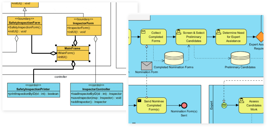
Visual Paradigm is not only a UML drawing tool but a UML modeler that supports a wide range of modeling features such as elements reusability, diagram & element transformation, syntax validation, custom properties, etc.
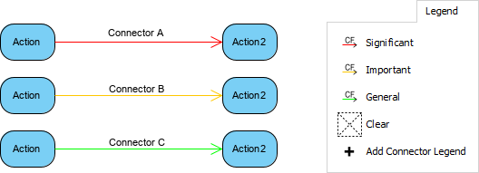
Make your design attractive by applying different shapes and line formats.
To achieve success in visual modeling, your Tool and Process must evolve alongside modern technology. Visual Paradigm integrates Generative AI to automate notation and streamline your development lifecycle.
AI Chatbot (Conversational Modeling): Turn plain-language descriptions into diagrams. You can iteratively refine models by asking the chatbot to execute changes, such as renaming parts, adding components, or modifying structural relationships.
AI-Assisted Class Diagram Generator: A specialized wizard that guides you step-by-step from raw project scope to a fully mapped software architecture. It systematically extracts classes, defines attributes, maps operations, and structures object relationships.
AI Textual Analysis Tool: Scans unstructured problem domain documents or requirements to identify critical core domain concepts, entities, and actions to lay down initial design foundations.
AI Use Case Refinement App: Automatically injects structural depth into basic use case models by calculating, identifying, and populating critical <> and <> relationships.
Use Case to Activity Diagram Generator: Transforms detailed text-based narratives and functional requirement stories into behavioral UML Activity Diagrams instantly.
The AI engine provides generation, structural validation, and conversational refactoring for all 14 standard UML 2.x formats, including:
Structural Diagrams: Class, Object, Component, Deployment, Package, Composite Structure, and Profile Diagrams.
Behavioral Diagrams: Use Case, Activity, State Machine, Sequence, Communication, Timing, and Interaction Overview Diagrams.
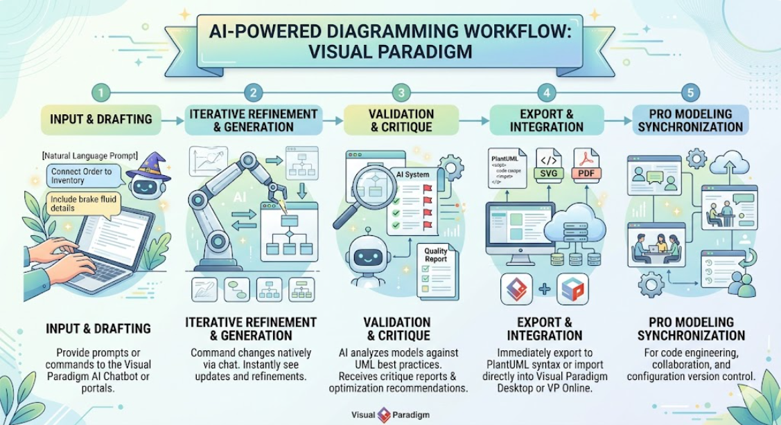
[ Natural Language Prompt ] ──> [ AI Chatbot / Wizard ] ──> [ PlantUML Code / SVG Preview ] ──> [ Import to Desktop / Web Workspace ]
Drafting: You supply text inputs to the Visual Paradigm AI Chatbot or online app portals.
Iterative Refinement: You command changes natively via chat (e.g., "Connect Order to Inventory" or "Include brake fluid details").
Validation & Quality Reports: The AI analyzes your model against established UML best practices to generate critique reports and maintainability optimization recommendations.
Pro Modeling Synchronization: Drafts can be immediately exported to PlantUML syntax or fully imported directly into Visual Paradigm Desktop or VP Online workspaces for code engineering, collaboration, and configuration version control.
Web Portal / AI Apps: Accessible via browser; specific generators require a Visual Paradigm Online Combo plan or higher.
Desktop App Integration: Embedded directly inside the software interface for Professional or Enterprise Edition licenses with active maintenance plans.
Web or cloud diagrammers may seem quite attractive initially with zero configuration, but they are very poor in terms of performance or capabilities on enterprise scale features when modeling complex diagrams
A model (such as a class) had already been created in a diagram cannot be referenced elsewhere within the diagram as a view (referenced shape) or in other diagram and don't mention about sharing among model elements in different projects, thus not suitable for enterprise scale modeling
All diagrams are separate piece of work without any traceability among them
No strong supporting toolset to unleash the full power of UML for serving on different activities required to be performed in software development such as teamwork, agile development, UX modeling, code engineering, enterprise project management and etc.
Diagramming tool like Visio only suitable for drawing simple diagrams and lacks good editing feature for complex diagrams layout and modification. What you get is a set of standard alone diagrams that are not powerful enough to scale-up with the entire software development process
Not like other UML diagramming tool with very limited support in UML notations, Visual Paradigm support the latest UML 2.x standard with 14 different types of diagram
Related visual modeling standards support such as BPMN, Mind map, Textual Analysis, Project Management Toolset (ArchiMate, Fishbone, Pert, Gantt, WBS, Radar Chart and many more!)
Apply use case modeling seamlessly with agile development by integrating use cases with story map for backlog management, release planning.
Send multiple sources of visual models (requirements) to agile product backlog such as identifying requirements from use cases, activities in UML Activity Diagram, tasks or activities from BPMN or nodes from mind map diagram.
Identify large requirement such as use case and transform them to be a set of manageable user stories or epics at your own choices and accommodate them a manageable story map structure
Once you transform use cases into related user story, they can be further breakdown into tasks and can subsequently be managed automatically by the task manager
Generate code from class and state diagrams for the popular programming languages
Generate database from ERDs and subsequently to class diagrams seamlessly mapping objects to relational database using Hibernate framework (support the most popular databases in the market)
Integrate Visual Paradigm with leading IDEs including Visual Studio, IntelliJ, NetBeans, Eclipse and Android Studio
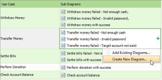
Support model traceability through model references (one model with multiple views), sub-diagrams model elaboration, reference visual models across multiple projects, annotations and reference attachments
Generate sequence diagrams or activity diagram from use case scenarios
Elaborate use case scenarios with wireframe tools
Identify classes from sequence diagrams and related model from one to another through the Model Transitor feature.
Simply drag & drop model elements or diagrams created to compose your own reports and output to it to a desirable format such as Word, PDF or HTML.
Alternatively, you can embed the model elements or diagrams from the Visual Paradigm project into the content of your corporate report or document with the Fill-in Documentation Composer.
Your team can concurrently edit the UML project with automatic version control, modification merge and conflicts resolution
Furthermore, you can share, discuss and comments diagrams or models online over the cloud through the PostMania feature
Attach and classify references and document into a handy, visual File Cabinet
The first phase of Web Diagram online feature is in place (including BPMN, business process Diagram, ArchiMate® Diagram, class diagram, use case diagram, sequence diagram, flow chart PERT, ITIL, AWS, and Microsoft Azure diagram), now all the existing Visual Paradigm users can take advantage of web diagrams online with no additional cost.
Now, you can try sample diagram online in the Visual Paradigm Community Circle by importing them straight to you application for learning and experiment or adopt the off-the-shelf templates for solving your problems.
The journey from conceptual requirements to deployable software systems demands more than just coding skill—it requires disciplined visualization, clear communication, and intelligent tooling. As this case study demonstrates, visual modeling grounded in UML principles, supported by adaptable processes, and empowered by modern AI-enhanced tools creates a transformative foundation for software development success.
Visual Paradigm exemplifies how the "Triangle of Success"—notation, process, and tool—can be modernized for today's challenges. By integrating Generative AI capabilities, teams can now accelerate the initial modeling phase through natural language interaction while maintaining the rigor and traceability required for enterprise-scale projects. The ability to transform textual requirements into structured diagrams, refine models conversationally, and synchronize designs across agile workflows, code generation, and documentation represents a significant evolution in how we approach system design.
For organizations navigating digital transformation, legacy modernization, or rapid product innovation, adopting an intelligent visual modeling ecosystem is no longer optional—it is strategic. Teams that leverage these capabilities gain clearer alignment with stakeholders, reduce rework through early validation, and accelerate time-to-market without sacrificing architectural quality. As software continues to drive competitive advantage across industries, the organizations that master the art and science of intelligent visual modeling will be best positioned to build systems that are not only functional, but resilient, maintainable, and ready for the future.