
In the rapidly evolving landscape of systems engineering, the transition from SysML v1 to SysML v2 represents more than a version update—it signifies a fundamental paradigm shift toward precision, executability, and tool-agnostic interoperability. As complex cyber-physical systems like autonomous drones, smart infrastructure, and integrated aerospace platforms grow in sophistication, traditional modeling approaches struggle to keep pace with the demands for verifiable requirements, unambiguous semantics, and seamless digital thread integration.
This case study presents a comprehensive, hands-on exploration of SysML v2 textual modeling through the development of a Drone System Context model. By walking through architectural blueprints, grammar mechanics, and implementation best practices, we demonstrate how SysML v2's formal textual syntax enables engineers to build rigorous, analyzable, and tool-interoperable system specifications. Whether you are a systems architect, requirements engineer, or model-based systems engineering (MBSE) practitioner, this guide provides the conceptual foundation and practical patterns needed to leverage SysML v2 for next-generation system design.
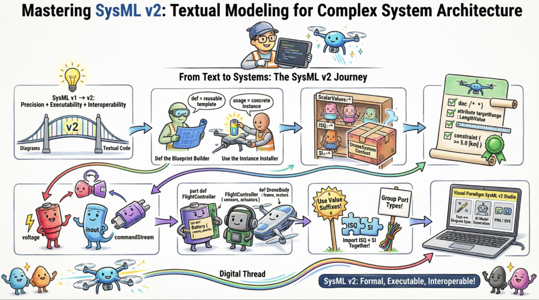
This guide breaks down the core elements, system architecture principles, and grammar rules demonstrated in your fully corrected, operational SysML v2 model.
package DroneSystemContext {
    private import ScalarValues::*;
    private import ISQ::*;
    private import SI::*;

    // ==========================================
    // 1. REQUIREMENTS DEFINITIONS
    // ==========================================
    requirement def RangeRequirement {
        doc /* The drone must achieve a minimum operational range. */
        attribute targetRange : LengthValue;
        constraint { targetRange >= 5.0 [km] }
    }

    // ==========================================
    // 2. STRUCTURAL DEFINITIONS
    // ==========================================
    port def PowerPort {
        out attribute voltage : ElectricPotentialValue;
        in attribute current : ElectricCurrentValue;
    }

    port def DataPort {
        inout item commandStream;
    }

    part def Battery {
        attribute capacity : EnergyValue;
        port powerOut : PowerPort;
    }

    part def FlightController {
        port powerIn : PowerPort;
        port dataIO : DataPort;

        action processTelemetry;
    }
}
SysML v2 moves away from SysML v1's UML profile dependencies, utilizing a precise textual grammar built on foundational engineering primitives.
Every structural or behavioral component in SysML v2 is governed by a strict division between its type definition and its concrete usage:
Definition (def): Creates an independent, reusable blueprint (e.g., part def Battery, port def PowerPort). It defines the internal parameters, ports, and logic that all instances of this type will inherit.
Usage: Instantiates a definition inside another element to construct system hierarchies (e.g., declaring a specific battery within an aircraft blueprint, written as part mainBattery : Battery;).
package: Establishes the foundational structural boundary. It groups related elements together to enforce a modular design.
private import: Controls element visibility and limits namespace pollution.
ScalarValues::*: Imports primitive types like Real, Integer, Boolean, and String.
ISQ::*: Imports the International System of Quantities. This provides the exact value types (e.g., LengthValue, EnergyValue) needed to represent physical quantities with mathematical data types rather than abstract dimensions.
SI::*: Imports the International System of Units. This unlocks specific measurement prefixes and literal units (e.g., km, V, mA, J) used inside constraint blocks.
The requirement def block replaces the generic text callouts of older systems engineering languages with verifiable, executable constraints.
doc /* ... */: Embedded string container that holds the plain-text description of the requirement. This is easily read by automated external PLM or Requirements Management tools.
attribute: Declares a value-bound mathematical property (targetRange) tied directly to a scalar quantity kind (LengthValue).
constraint { ... }: Defines a boolean equation that evaluates system performance. The bracketed expression [km] binds the scalar unit directly to the numeric value (5.0), allowing the compiler to flag errors if the input does not match the required unit type.
The port def establishes how a block communicates with external components.
out attribute voltage : ElectricPotentialValue;: Emits a physical value to the system boundary. It uses the precise scientific name ElectricPotentialValue required by the ISQ specification instead of generic designations like "Voltage".
in attribute current : ElectricCurrentValue;: Receives an ongoing stream from a connected source.
inout item commandStream;: Configures a bi-directional data conduit. It uses the item keyword rather than attribute because it represents discrete data structures or hardware messages instead of constant scalar values.
The part def defines structural system entities (components, subsystems, or assemblies).
Attribute Hosting: Declares fixed or varying physical traits (like attribute capacity : EnergyValue;) that describe the system component.
Port Incorporation: Exposes the component's connection boundaries (such as port powerOut : PowerPort;) so it can interact with other parts when building larger systems.
Behavior Integration: Embedded actions (like action processTelemetry;) declare localized functions directly inside the component's structural scope. This explicitly shows which part of the hardware executes a given function.
Always Use Value Suffixes for Data Types: Never map an attribute directly to an abstract quantity dimension like Length, Voltage, or Current. Always use their corresponding value-holding equivalents (LengthValue, ElectricPotentialValue, ElectricCurrentValue) to avoid type-conformity errors.
Import Libraries in Pairs: Whenever you import the quantity library (private import ISQ::*;), ensure you also import the unit library (private import SI::*;). This provides both the data types and the specific unit expressions (like [km]) needed for your mathematical expressions.
Explicitly Group Port Types: Always use matching prefixes (such as combining out attribute or in attribute) when declaring ports that pass value data streams. This ensures your interfaces align correctly when you begin modeling system interconnections.
Visual Paradigm officially supports SysML v2 modeling through its dedicated extension, Visual Paradigm SysML v2 Studio. This module delivers a synchronized "text-and-graphic" environment accessible both via the web browser and directly inside the Visual Paradigm Desktop Application (for Professional and Enterprise license holders).
The tool provides full modeling capabilities for the updated SysML v2 Core Specification:
Structural: Blocks, parts, ports, allocations, and connection flows.
Behavioral: Actions, states, use cases, and sequence flows.
Specifications: Formal requirement def blocks and embedded constraint logic.
Instead of using manual drag-and-drop shapes, models are authored using textual code.
Real-time Engine Sync: A built-in code editor instantly compiles text into live-rendered diagram previews.
Code Assistant: Employs Monaco-based features including syntax highlighting, bracket matching, and auto-completion.
Compiler Diagnostics: Features a dedicated "Problems Pane" that provides real-time validation feedback to flag grammar and type resolution issues.
Engineers do not need to manually arrange layout shapes.
Automatic Layout Engine: Automatically generates and routes visual diagrams for Use Case, Activity, State, and Sequence representations.
Multi-View Scopes: Switches the active element view seamlessly between hierarchical tree structures, state views, interconnection paths, and action views.
Styling & Export: Supports customizing element compartment visibility, line routing styles, and inheriting attributes. Finished diagrams can be exported natively as high-quality PNG or SVG images.
Model Generation: Uses integrated natural language prompts to automatically draft complete, syntactically accurate SysML v2 files (such as populating target blocks, modules, and sub-systems).
Automated Documentation: Translates modeled code structures into comprehensive markdown engineering reports.
The adoption of SysML v2 textual modeling represents a transformative step forward for systems engineering practice. By embracing a formal, grammar-driven syntax grounded in international standards for quantities and units, engineers can now create specifications that are not only human-readable but also machine-verifiable, executable, and interoperable across the digital engineering ecosystem.
Through the Drone System Context case study, we have demonstrated how core SysML v2 constructs—requirements with embedded constraints, strongly-typed ports with explicit flow directionality, and modular part definitions with integrated behavior—enable precise, analyzable system architectures. When paired with modern tooling like Visual Paradigm SysML v2 Studio, which offers real-time text-to-diagram synchronization, intelligent code assistance, and AI-powered model generation, the barrier to entry for rigorous MBSE practices is significantly lowered.
As industry continues to demand higher assurance, traceability, and automation in system development, mastering SysML v2's textual paradigm is no longer optional—it is essential. By internalizing the definition-usage pattern, respecting namespace hygiene, and adhering to value-type discipline, systems engineers can build models that scale with complexity, integrate with simulation and verification tools, and serve as the single source of truth throughout the system lifecycle. The future of systems engineering is textual, formal, and executable—and SysML v2 is the language that makes it possible.
Visual Paradigm SysML v2 Studio – Features Overview: Comprehensive feature description of Visual Paradigm's dedicated SysML v2 modeling extension, including text-and-graphic synchronization, web and desktop accessibility, and support for the full SysML v2 Core Specification.
SysML v2 Studio Competitive Advantages Launch Announcement: Official release notes detailing the advanced capabilities of Visual Paradigm SysML v2 Studio, including Monaco-based code editing, real-time diagram rendering, AI-assisted model generation, and automated documentation features for Professional and Enterprise license holders.

