The UML Class diagram is a graphical notation used to construct and visualize object oriented systems. A class diagram in the Unified Modeling Language (UML) is a type of static structure diagram that describes the structure of a system by showing the system's:
Are you looking for a Free UML tool for learning UML faster, easier and quicker? Visual Paradigm Community Edition is a UML software that supports all UML diagram types. It is an international award-winning UML modeler, and yet it is easy-to-use, intuitive & completely free.
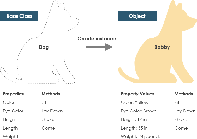
Free DownloadA Class is a blueprint for an object. Objects and classes go hand in hand. We can't talk about one without talking about the other. And the entire point of Object-Oriented Design is not about objects, it's about classes, because we use classes to create objects. So a class describes what an object will be, but it isn't the object itself.
In fact, classes describe the type of objects, while objects are usable instances of classes. Each Object was built from the same set of blueprints and therefore contains the same components (properties and methods). The standard meaning is that an object is an instance of a class and object - Objects have states and behaviors.
A dog has states - color, name, breed as well as behaviors -wagging, barking, eating. An object is an instance of a class.
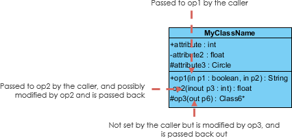
A class represent a concept which encapsulates state (attributes) and behavior (operations). Each attribute has a type. Each operation has a signature. The class name is the only mandatory information.
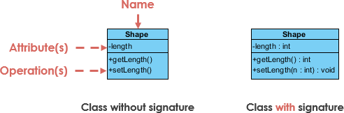
Class Name:
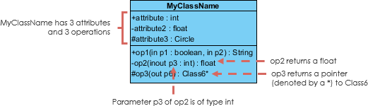
Class Attributes:
Class Operations (Methods):
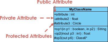
The +, - and # symbols before an attribute and operation name in a class denote the visibility of the attribute and operation.
Each parameter in an operation (method) may be denoted as in, out or inout which specifies its direction with respect to the caller. This directionality is shown before the parameter name.
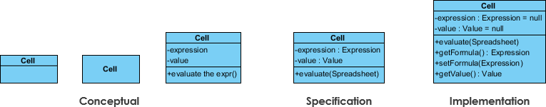
The choice of perspective depends on how far along you are in the development process. During the formulation of a domain model, for example, you would seldom move past the conceptual perspective. Analysis models will typically feature a mix of conceptual and specification perspectives. Design model development will typically start with heavy emphasis on the specification perspective, and evolve into the implementation perspective.
A diagram can be interpreted from various perspectives:
The perspective affects the amount of detail to be supplied and the kinds of relationships worth presenting. As we mentioned above, the class name is the only mandatory information.
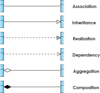
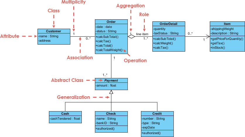
UML is not just about pretty pictures. If used correctly, UML precisely conveys how code should be implemented from diagrams. If precisely interpreted, the implemented code will correctly reflect the intent of the designer. Can you describe what each of the relationships mean relative to your target programming language shown in the Figure below?
If you can't yet recognize them, no problem this section is meant to help you to understand UML class relationships. A class may be involved in one or more relationships with other classes. A relationship can be one of the following types:
A generalization is a taxonomic relationship between a more general classifier and a more specific classifier. Each instance of the specific classifier is also an indirect instance of the general classifier. Thus, the specific classifier inherits the features of the more general classifier.
The figure below shows an example of inheritance hierarchy. SubClass1 and SubClass2 are derived from SuperClass. The relationship is displayed as a solid line with a hollow arrowhead that points from the child element to the parent element.
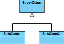
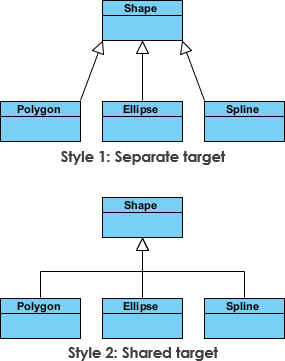
The figure below shows an inheritance example with two styles. Although the connectors are drawn differently, they are semantically equivalent.
Associations are relationships between classes in a UML Class Diagram. They are represented by a solid line between classes. Associations are typically named using a verb or verb phrase which reflects the real world problem domain.
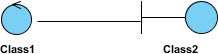
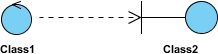
The figure below shows an example of simple association. There is an association that connects the <<control>> class Class1 and <<boundary>> class Class2. The relationship is displayed as a solid line connecting the two classes.
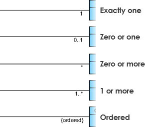
Cardinality is expressed in terms of:
A special type of association.
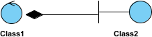
The figure below shows an example of aggregation. The relationship is displayed as a solid line with a unfilled diamond at the association end, which is connected to the class that represents the aggregate.

The figure below shows an example of composition. The relationship is displayed as a solid line with a filled diamond at the association end, which is connected to the class that represents the whole or composite.
An object of one class might use an object of another class in the code of a method. If the object is not stored in any field, then this is modeled as a dependency relationship.
The figure below shows an example of dependency. The relationship is displayed as a dashed line with an open arrow.
The figure below shows another example of dependency. The Person class might have a hasRead method with a Book parameter that returns true if the person has read the book (perhaps by checking some database).

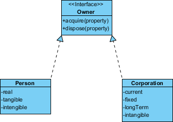
Realization is a relationship between the blueprint class and the object containing its respective implementation level details. This object is said to realize the blueprint class. In other words, you can understand this as the relationship between the interface and the implementing class.
For example, the Owner interface might specify methods for acquiring property and disposing of property. The Person and Corporation classes need to implement these methods, possibly in very different ways.
A class diagram may also have notes attached to classes or relationships.
You've learned what a Class Diagram is and how to draw a Class Diagram. It's time to draw a Class Diagram of your own. Get Visual Paradigm Community Edition, a free UML software, and create your own Class Diagram with the free Class Diagram tool. It's easy-to-use and intuitive.
Free DownloadLearning notation and relationships is easier when you can see them in action. Use our AI-powered ecosystem to generate accurate Class Diagrams from descriptions, helping you validate your understanding of attributes, visibility, and associations.
✨ AI Class Diagram Wizard: A dedicated step-by-step wizard to build classes with AI-suggested attributes and operations.
📋 Use Case Studio: Automatically identify domain classes and relationships directly from use case descriptions.
🏃 Agilien: Bridge Agile planning to design by generating Class Diagrams from Epics and User Stories.
🗄️ DB Modeler AI: Creates conceptual Class Diagrams as the foundation for database schema generation.
🏗️ MVC Architecture: Generates specialized Controller Class Diagrams to visualize system responsibilities.