
Composite Structure Diagram is one of the new artifacts added to UML 2.0. A composite structure diagram is a UML structural diagram that contains classes, interfaces, packages, and their relationships, and that provides a logical view of all, or part of a software system. It shows the internal structure (including parts and connectors) of a structured classifier or collaboration.
A composite structure diagram performs a similar role to a class diagram, but allows you to go into further detail in describing the internal structure of multiple classes and showing the interactions between them. You can graphically represent inner classes and parts and show associations both between and within classes.

Are you looking for a Free UML tool for learning UML faster, easier and quicker? Visual Paradigm Community Edition is a UML software that supports all UML diagram types. It is an international award-winning UML modeler, and yet it is easy-to-use, intuitive & completely free.
Free Download
Online Store
Suppose we are modeling a system for an online store. The client has told us that customers may join a membership program which will provide them with special offers and discounted shipping, so we have extended the customer object to provide a member and standard option.
Let's modeling the online store using a class diagram

We have a class for Item which may be aggregated by the Order class, which is composed by the Customer class which itself is composed by the StoreManager class. We have a lot of objects that end up within other objects.
Everything looks like it ends up inside StoreManager, so we can create a composite structure diagram to really see what it's made of.

In the example above, we can see:
Question: Are two diagram below expressing the same meaning?
Answer: In a class diagram the reference between Description and Pricing is ambiguous, strictly speaking, they are not exactly the same.

If we use a Composite Structure Diagram, the meaning of the containment of the association relationship is unambiguous.
We have seen examples of how Composite Structure diagrams are great at describing aggregation, but your models will also need to contain references to objects outside of the class you are modeling.
But what about the referencing an external object with Composite Structure Diagram like the example below?

The key composite structure entities identified in the UML 2.0 specification are structured classifiers, parts, ports, connectors, and collaborations.
A collaboration describes a structure of collaborating parts (roles). A collaboration is attached to an operation or a classifier through a Collaboration Use. You use a collaboration when you want to define only the roles and connections that are required to accomplish a specific goal of the collaboration.
For example, the goal of a collaboration can be to define the roles or the components of a classifier. By isolating the primary roles, a collaboration simplifes the structure and clarifies behavior in a model.
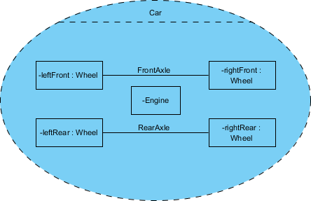
Example
In this example the Wheels and the Engine are the Parts of the Collaboration and the FrontAxle and the RearAxle are the Connectors. The Car is the Composite Structure that shows the parts and the connections between the parts.
A part is a diagram element that represents a set of one or more instances that a containing structured classifier owns. A part describes the role of an instance in a classifier. You can create parts in the structure compartment of a classifier, and in several UML diagrams such as composite structure, class, object, component, deployment, and package diagrams.
A port defines the interaction point between a classifier instance and its environment or between the behavior of the classifier and its internal parts.
Composite Structure diagram supports the ball-and-socket notation for the provided and required interfaces. Interfaces can be shown or hidden in the diagram as needed.
A line that represents a relationship in a model. When you model the internal structure of a classifier, you can use a connector to indicate a link between two or more instances of a part or a port. The connector defines the relationship between the objects or instances that are bound to roles in the same structured classifier and it identifies the communication between those roles. The product automatically specifies the kind of connector to create.
Let's develop the composite structure diagram for a computer system which include the following a list of the components:
We will assume for the moment that the mainboard is of the type that has a sound card and display adapter built in:

You've learned what a Composite Structure Diagram is and how to draw a Composite Structure Diagram. It's time to draw a Composite Structure Diagram of your own. Get Visual Paradigm Community Edition, a free UML software, and create your own Composite Structure Diagram with the free Composite Structure Diagram tool. It's easy-to-use and intuitive.
Free Download