
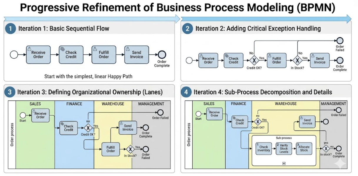
This case study demonstrates how Business Process Model and Notation (BPMN 2.0) can be systematically developed using a progressive refinement methodology. Rather than attempting to capture every detail in a single, overly complex diagram, the process modeling team iteratively evolves a high-level abstraction into a detailed, execution-ready blueprint. Starting from a simplified "happy path," the model is progressively enriched with business rules, organizational roles, exception handling, and task-level automation markers. The result is a clear, stakeholder-aligned, and technically precise process model that bridges the gap between business strategy and IT implementation.
Organization: Mid-market B2B Retail & Distribution Company
Process: Order-to-Fulfillment (Order Management)
Pain Points Prior to Modeling:
Objective: Create a standardized, unambiguous, and executable BPMN model that captures the end-to-end order management process, enables cross-functional alignment, and serves as a foundation for workflow automation.
The modeling team adopted a four-stage iterative approach, aligning with BPMN 2.0 best practices for diagram complexity management:
Each stage was validated with process owners before advancing to the next, ensuring stakeholder buy-in and diagram accuracy.
Objective: Establish a shared, high-level understanding of the primary process flow.
BPMN Elements Used:
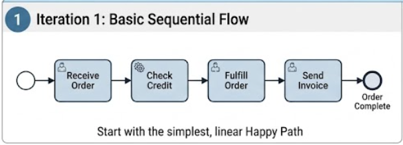
Process Flow:
Receive Order → Check Credit → Fulfill Order → Send Invoice → End
Value Delivered:
(Figure 1: Linear sequence flow representing the ideal, error-free order journey.)
Objective: Reflect real-world business rules, decision points, and potential failure paths.
BPMN Elements Introduced:
Enhanced Process Flow:
Check Credit: XOR Gateway evaluates credit status. If Fail, route to Order Failed end event.Check Stock (new task added to Fulfill Order): XOR Gateway evaluates inventory. If Out of Stock, route to backorder or cancellation path.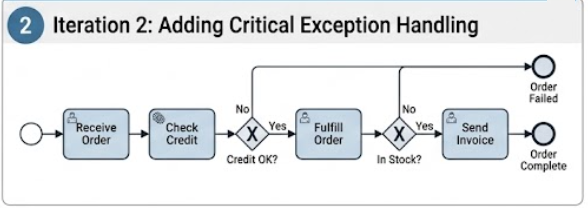
Value Delivered:
(Figure 2: Process diagram with XOR gateways, conditional sequence flows, and multiple end states.)
Objective: Clarify task ownership, identify handoff points, and expose departmental bottlenecks.
BPMN Elements Introduced:
Lane Structure:
Receive Order, Notify Customer of StatusCheck Credit, Generate & Send Invoice, Handle Payment ExceptionsCheck Stock, Pick & Pack, Ship Order, Update Inventory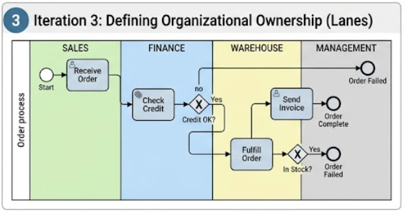
Value Delivered:
(Figure 3: Swimlane diagram showing task distribution across Sales, Finance, and Warehouse.)
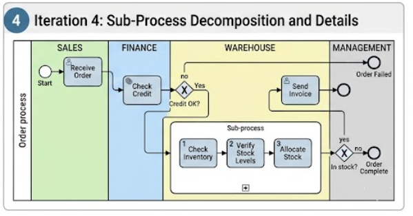
Objective: Prepare the model for automation, system integration, and operational execution.
BPMN Elements Introduced:
Decomposition Example:
Fulfill Order (collapsed) → Expands to:
Check Stock (Service Task – queries ERP inventory API)Pick Items (User Task – warehouse operator uses mobile scanner)Pack & Label (Manual Task – physical preparation)Ship Order (Service Task – integrates with carrier tracking system)Update Inventory (Script Task – automated database sync)Task Typing Guide Applied:
Value Delivered:
(Figure 4: Detailed diagram with expanded subprocesses, task type icons, and system integration markers.)
| Phase | Recommended Actions |
|---|---|
| Validation | Conduct process walk-throughs with lane owners. Use simulation tools to test bottleneck scenarios. |
| Tool Selection | Use BPMN-compliant modelers (e.g., Camunda Modeler, Signavio, Bizagi, Lucidchart) that support executable BPMN export. |
| Version Control | Store models in a centralized repository with change tracking, approval workflows, and semantic versioning. |
| Execution Readiness | Export to BPMN 2.0 XML, configure workflow engine, map user tasks to identity providers, and bind service tasks to APIs. |
Credit Approved = True).The progressive refinement of the Order Management process demonstrates how BPMN 2.0 can evolve from a high-level communication tool into a precise, execution-ready blueprint. By systematically introducing decision logic, organizational structure, and technical task typing, organizations can eliminate ambiguity, accelerate automation initiatives, and establish a single source of truth for cross-functional workflows. This case study reinforces that effective BPMN modeling is not about drawing the perfect diagram on the first attempt, but about iteratively refining clarity, accuracy, and operational relevance.
| Element | Symbol/Icon | Purpose |
|---|---|---|
| Start Event | Thin circle | Initiates the process |
| End Event | Thick circle | Terminates the process or path |
| Task | Rounded rectangle | Represents a unit of work |
| Exclusive Gateway (XOR) | Diamond with X |
Routes flow to exactly one path based on condition |
| Parallel Gateway (AND) | Diamond with + |
Splits/merges concurrent flows |
| Pool | Large rectangle | Represents a major participant/organization |
| Lane | Horizontal subdivision | Represents a role/department within a pool |
| Sub-Process | Task with + (collapsed) or expanded box |
Groups related tasks |
| Message Flow | Dashed arrow with open head | Communication between separate pools |
Note: All diagrams referenced in this case study conform to OMG BPMN 2.0 specification and are ready for export to executable workflow engines when mapped to appropriate technical configurations.

