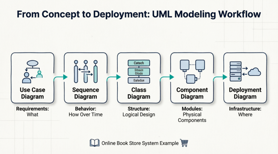
Unified Modeling Language (UML) serves as the universal blueprint for software development, enabling teams to visualize, specify, construct, and document complex systems before a single line of code is written. This comprehensive guide walks you through the complete UML modeling journey using a practical, real-world example: an Online Book Store System.
By following a logical progression from high-level requirements to physical infrastructure, you'll discover how five essential UML diagrams work together to transform abstract business needs into a deployable technical architecture. Whether you're a product manager clarifying scope, a developer implementing features, or an architect designing scalable systems, this guide demonstrates how systematic UML modeling reduces ambiguity, improves communication, and accelerates delivery. Let's explore how to model a complete e-commerce solution from the ground up.
Before diving into the diagrams, here is the "problem" we are modeling:
An online book store needs to allow customers to browse books, search for specific titles, add books to a cart, and checkout using a payment gateway. Administrators need to manage the book inventory (add/edit/remove books).
This diagram defines the system boundary and the interactions between the system and its users (Actors). It describes what the system does from a functional requirement perspective, not how it does it.
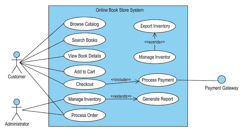
To select a use case, we choose Checkout. A simple oval isn't enough for developers; we must detail the flow of events.
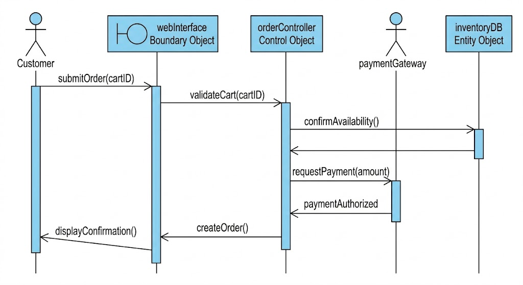
The industry standard for detailing a Use Case's internal logic is the Sequence Diagram. It shows how objects interact over time to fulfill the scenario, introducing the first hint of system realization (Control objects and Entity objects).
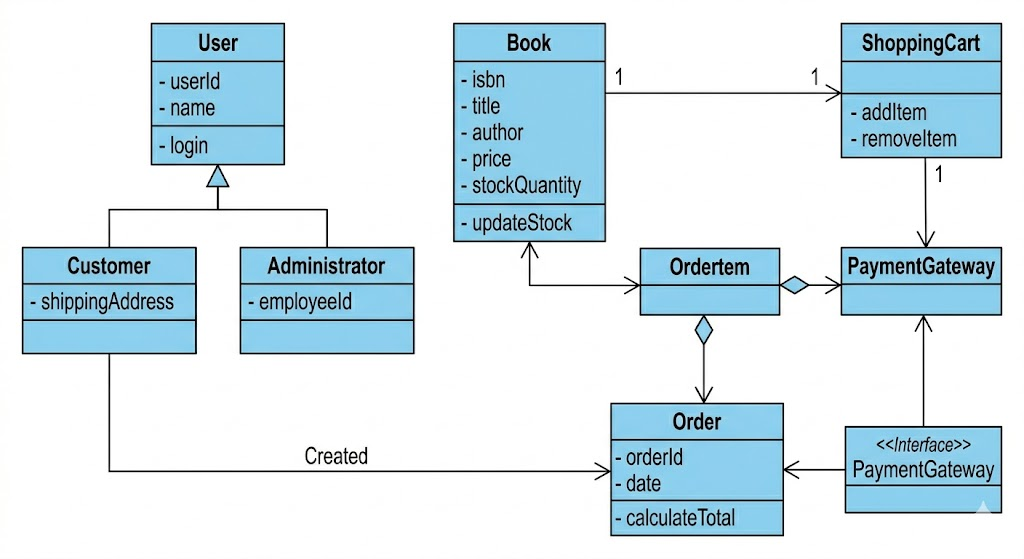
The Sequence Diagram showed us interaction logic. To support that interaction, we need structural blueprints. The Class Diagram describes the types of objects (Classes) that exist in the system, their internal data (Attributes), their behavior (Operations), and how they relate statically. This is the foundation for object-oriented coding.
Observe how entities from the Sequence Diagram (inventoryDB, which holds Book data) and relationships defined in Use Cases (e.g., Manage Inventory) are formalized here.
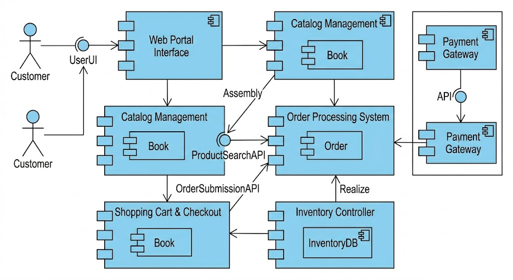
The Class Diagram is too detailed for high-level assembly. The Component Diagram packs related classes and data entities into modular, replaceable units (Components). It shows the system's wiring, focusing on Interfaces (the plugs and sockets) that allow components to interact while hiding internal complexity.
This diagram organizes the logical concepts (like Book and Order classes) into physical modules (Catalog Management, Order Processing) that can be developed and deployed independently.
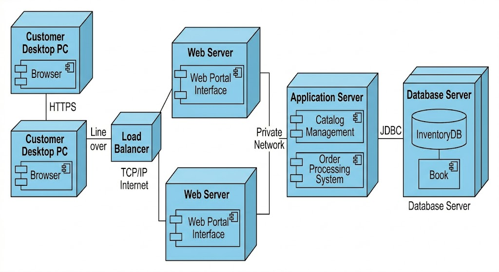
The final diagram shows the physical architecture: where the software components will exist in the real world. It assigns the software (Components from the previous diagram, now shown as Artifacts) to physical hardware (Nodes, like servers, PCs, or cloud instances) and details the networking protocols connecting them.
It shows the implementation topology.
Visual Paradigm is a comprehensive UML modeling platform that supports all 14 standard UML 2.x diagram types across its desktop, online, and AI-integrated versions.
The platform provides full support for both structural and behavioral UML diagrams:
Structural Diagrams: Class Diagram (with real-time code synchronization), Object Diagram, Component Diagram, Composite Structure Diagram, Package Diagram, and Deployment Diagram.
Behavioral Diagrams: Use Case Diagram (with flow of events documentation), Sequence Diagram, Communication Diagram, State Machine Diagram, Activity Diagram, Timing Diagram, and Interaction Overview Diagram.
Visual Paradigm offers several advanced tools to streamline the modeling process:
AI-Powered Generation: Users can generate diagrams like Use Case, Class, and Sequence diagrams from simple textual descriptions using the AI Diagram Generator.
Code Engineering: Supports bi-directional synchronization (round-trip engineering) between UML models and code for over 10 languages, including Java, C#, and C++.
IDE Integration: Integrates directly with popular environments like Eclipse, IntelliJ IDEA, NetBeans, and Visual Studio.
Interoperability: Allows importing projects from other CASE tools like Rational Rose and supports XMI import/export.
Collaborative Design: Teams can design and comment on diagrams simultaneously through Visual Paradigm Cloud.
Would you like to know more about how to reverse engineer existing code into UML diagrams?
Modeling an Online Book Store System through the lens of UML demonstrates the power of visual thinking in software engineering. Starting with Use Case Diagrams to capture stakeholder requirements, progressing through Sequence and Class Diagrams to define behavior and structure, then abstracting to Component Diagrams for modular design, and finally mapping to Deployment Diagrams for infrastructure planning—this end-to-end approach ensures clarity, reduces rework, and aligns cross-functional teams.
UML is not merely documentation; it is a living language for collaboration between product, design, and engineering. By leveraging modern tools like Visual Paradigm, teams can accelerate this process with AI assistance, code synchronization, and real-time collaboration. Whether you're architecting a new system or refining an existing one, adopting a disciplined UML workflow transforms ambiguity into actionable blueprints and ideas into robust, scalable software. Start modeling your next project today—and watch complexity give way to clarity.