The Documentation Dilemma: Clarity Without Compromise
Software architecture documentation often falls into one of two traps: it's either too abstract to guide implementation, or so detailed that stakeholders disengage. Executives need to understand system boundaries and business value, while developers require precise behavioral specs and code-level contracts. How do you serve both audiences without maintaining two disconnected sets of diagrams?
The answer lies in a strategic partnership: the C4 model and UML.
The C4 model (Context, Containers, Components, Code) provides a hierarchical, audience-friendly narrative that scales from "what does this system do?" to "how is this module structured?" Meanwhile, UML (Unified Modeling Language) delivers the formal precision needed for complex workflows, state management, and deployment specifics. Used in isolation, each has limitations. Used together, they create a cohesive documentation ecosystem that bridges strategy and execution.
In this guide, you'll learn:
Whether you're documenting a greenfield microservices platform or modernizing a legacy monolith, this integrated approach helps you create documentation that stakeholders actually use—and developers trust.
The C4 model (Context, Containers, Components, and Code) and UML (Unified Modeling Language) complement each other exceptionally well. C4 excels at providing a hierarchical, audience-friendly "big-picture" narrative of software architecture through progressive levels of abstraction. UML supplies the "fine print" with precise technical details, behavioral workflows, and implementation specifics.
This integration lets teams communicate high-level structure to stakeholders while giving developers the detailed blueprints they need. C4 is primarily structural and notation-independent, making it flexible for different audiences. UML adds depth for complex internal logic, runtime interactions, and deployment realities.
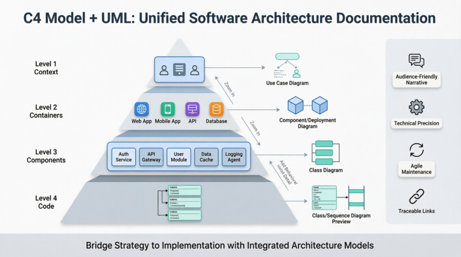
C4's Level 4 (Code) is explicitly suited for detailed views, where UML diagrams shine. You can also embed or link UML for behavioral modeling (where C4 is weaker) and enhanced deployment views.
Map UML diagrams to specific C4 needs for a synergistic approach:
Best Practice Tip: Start with C4 for the overall hierarchy and "zoom in" selectively with UML only where complexity demands it. Avoid over-detailing every C4 element—focus UML on critical or intricate parts to keep documentation lean.
Here's an expanded table based on common use cases:
| C4 Level / Need | Recommended UML Diagram | Example Use Case |
|---|---|---|
| Level 4: Code | UML Class Diagram | Inside a "Payment Service" C4 Component: Detail PaymentProcessor, Invoice, Transaction classes, associations, and methods. |
| Workflow / Interactions | UML Sequence Diagram | Show step-by-step API calls and responses between "Frontend" container and "Auth" or "Payment" services during login/checkout. |
| State Management | UML State Machine Diagram | Model an "Order" entity's lifecycle states and transitions in an e-commerce system. |
| Infrastructure / Deployment | UML Deployment Diagram | Map C4 "Web Server" container to specific nodes, execution environments, and hardware details. |
| Dynamic/Behavioral Views | UML Activity or Communication | Elaborate high-level C4 dynamic views with precise control flows or message numbering. |
In practice, link diagrams so high-level C4 changes can propagate awareness to detailed UML views (tools with model synchronization help here).
Modeling tools support combining C4 and UML:
Yes, here's a basic example using C4-PlantUML for a container and how you might reference or combine it with a UML Sequence Diagram (in the same file or separate, linked in documentation):
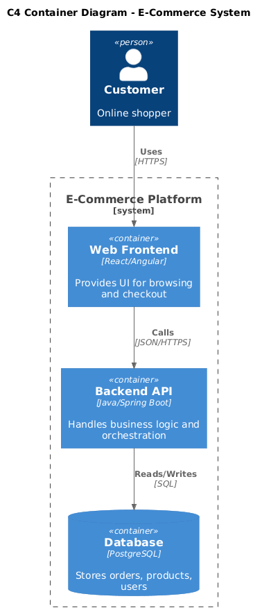
@startuml
!include https://raw.githubusercontent.com/plantuml-stdlib/C4-PlantUML/master/C4_Container.puml

title C4 Container Diagram - E-Commerce System

Person(customer, "Customer", "Online shopper")
System_Boundary(c1, "E-Commerce Platform") {
    Container(spa, "Web Frontend", "React/Angular", "Provides UI for browsing and checkout")
    Container(api, "Backend API", "Java/Spring Boot", "Handles business logic and orchestration")
    ContainerDb(db, "Database", "PostgreSQL", "Stores orders, products, users")
}

Rel(customer, spa, "Uses", "HTTPS")
Rel(spa, api, "Calls", "JSON/HTTPS")
Rel(api, db, "Reads/Writes", "SQL")

@enduml
For the detailed behavioral view, you could add or reference a UML Sequence in the same PlantUML file or separate artifact:
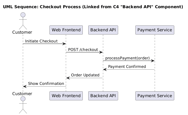
@startuml
title UML Sequence: Checkout Process (Linked from C4 "Backend API" Component)

actor Customer
participant "Web Frontend" as SPA
participant "Backend API" as API
participant "Payment Service" as Payment

Customer -> SPA: Initiate Checkout
SPA -> API: POST /checkout
API -> Payment: processPayment(order)
Payment --> API: Payment Confirmed
API --> SPA: Order Updated
SPA --> Customer: Show Confirmation

@enduml
In tools like Visual Paradigm or documentation platforms, hyperlink the C4 component to the Sequence diagram for easy navigation.
In real projects (such as enterprise e-commerce platforms or microservices-based systems we've worked on), our team leverages Visual Paradigm as a central hub for testing and refining C4 + UML integration. Its recent full C4 support (dedicated shapes/templates for all levels), combined with robust UML capabilities and AI features, makes it highly effective.
Typical Workflow in a Real Project:
Benefits We've Seen:
Tips from Our Usage:
This C4 + UML approach, especially when powered by a capable platform like Visual Paradigm, delivers clear, actionable architecture documentation that serves both strategic and technical needs. It bridges the gap between abstract overviews and implementable details effectively.
Architecture Documentation That Works for Everyone
Integrating the C4 model with UML isn't about adding more diagrams—it's about creating the right diagrams, at the right level of abstraction, for the right audience. By using C4 as your narrative backbone and selectively augmenting it with UML's precision, you build a documentation system that:
✅ Scales with your audience: Executives grasp the Context diagram; developers dive into linked Class or Sequence diagrams—without confusion.
✅ Reduces cognitive load: No more "spaghetti diagrams." Each view has a clear purpose and scope.
✅ Stays maintainable: Focus detailed UML modeling only where complexity demands it (typically 20–30% of components).
✅ Enables traceability: Link C4 elements to UML artifacts so changes propagate awareness, not drift.
✅ Supports agile delivery: Lightweight C4 updates keep pace with sprints; UML details evolve alongside code.
Great architecture documentation doesn't just describe a system—it enables the people building and using it. By combining C4's clarity with UML's rigor, you create a shared language that turns architectural intent into executable reality.
"The best diagrams aren't the most detailed—they're the most useful."
Ready to put this into practice? Revisit your current architecture docs today: identify one high-level C4 view that could benefit from a linked UML detail. That single connection is the first step toward documentation that truly scales with your team's needs.
Have questions about adapting this approach to your stack? Share your context—we'd love to help you refine the pattern. 🚀