PlantUML Deployment Diagram Generator

Visually design and generate complex PlantUML deployment diagrams without writing a single line of code.

  • PlantUML Deployment Diagram Generator
  • PlantUML Deployment Diagram Generator
  • PlantUML Deployment Diagram Generator

The PlantUML Deployment Diagram Generator makes professional architecture and deployment diagramming easy-no PlantUML syntax required. Model, preview, and export diagrams for system architecture, CI/CD pipelines, and infrastructure with a fast, wizard-driven workflow.

Purpose and Benefits

Define and communicate deployment topologies, system structures, and workflows with a visual editor-accelerating collaboration, reducing errors, and ensuring consistency.

  • Forms-Based Editor: Add, edit, and group entities and containers visually with intuitive forms.
  • Real-Time Preview: Toggle instantly between auto-generated PlantUML code and the SVG diagram output.
  • Customization: Rich selection of entity/container types, colors, and labels; intelligent validation checks for unique aliases and correct syntax.
  • Collaboration & Versioning: Save/load complete diagrams via JSON files-share, resume, and version-control work with your team.
  • Example Gallery & Themes: Start from common architecture patterns (e.g., three-tier, microservices) with light/dark mode for comfort.

How It Works: Step-by-Step Guide

Build diagrams through an efficient, linear workflow-from naming, through modeling architecture, to exporting shareable code and images.

Step 1: Set Diagram Title

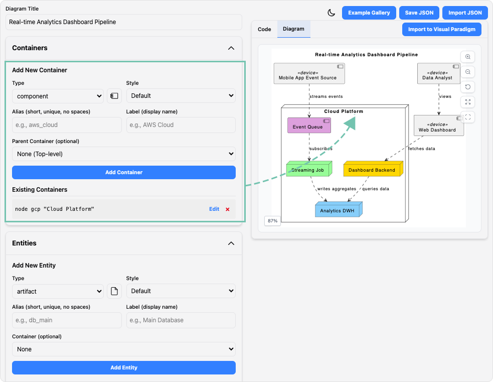
Enter a descriptive name at the top of the editor panel to frame your diagram.


Step 2: Define Containers

Add containers for logical grouping (e.g., cloud, node, frame); nest as needed for architecture layers.


Step 3: Add Entities

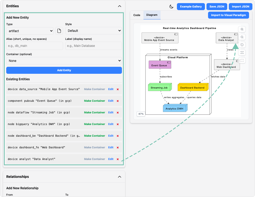
Populate the system with components, actors, databases, queues, and more, each with editable labels and unique aliases.


Step 4: Create Relationships

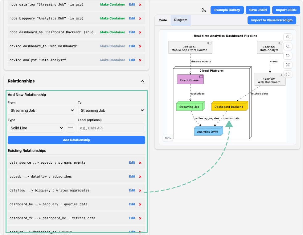
Connect entities and containers using clear relationship lines and labels for precise architectural flow.


Step 5: Add Notes

Attach floating or contextual notes to clarify design decisions and add documentation.


Step 6: Review, Export & Collaborate

Preview the PlantUML code and rendered SVG side-by-side, export your work, and manage diagrams in JSON for sharing and version control.

Use Cases

  • Engineers & Developers: Document live system deployments or build architecture for new products.
  • Architects: Design and communicate high-level system structures and cloud infrastructure.
  • DevOps Teams: Visualize CI/CD pipelines and cloud resource relationships for automation or audit.
  • Technical Managers & Team Leads: Create and share unambiguous diagrams with stakeholders and diverse teams.
  • Educators & Students: Learn architecture concepts and PlantUML syntax visually and interactively.

Tips & Best Practices

  • Start from an example diagram, then customize for your architecture.
  • Use clear, unique aliases for all entities and containers for reliable code generation.
  • Use notes for design clarifications and handoff documentation.
  • Save JSON files as assets in version control for multi-team collaboration.

Turn every software project into a successful one.

We use cookies to offer you a better experience. By visiting our website, you agree to the use of cookies as described in our Cookie Policy.

OK