How to Link with Classes in Use Case Flow of Events
The Flow of Events tool is invaluable for describing and documenting user flows. Often, these flows include references to data structures. Traditionally, this involved manual entry. This tutorial explores a more efficient approach.
However, as your project evolves, data structures may undergo changes. Such modifications can render references in your flows of events outdated, sometimes without immediate notice. If these inconsistencies come to light, a manual remedy would involve searching for all outdated entries and updating them one by one. This manual process is not only time-consuming but also prone to accuracy issues due to the high volume of input. Furthermore, what if you missed a crucial flow of events in your collection of use case diagrams?
But what if there was a way to synchronize these changes automatically? Fortunately, there is.
What This Tutorial Covers
In this tutorial, we will show you how to add classes and attributes to a flow of events such that the flow of events will stay up-to-date with any changes made to the data structures being referenced.
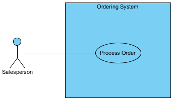
We will be using a simple use case diagram example below.
Software Tool We'll Be Using
For this tutorial, we will be using Visual Paradigm. You are welcome to download a free 30-day evaluation copy of Visual Paradigm to follow along with the example. No registration, email address, or obligation is required.
Steps to Create a Class Diagram
We will now create a class diagram to document our data structure, elaborating on the use case Process Order.
-
In the use case diagram, select the use case Process Order and click the Sub Diagrams icon.

Select Add > Other Diagrams > UML Diagrams > Class Diagram.
- In the new class diagram, click on any white space. You will notice that the diagram is initially named Process Order, derived from the use case. You may change it to something else if desired; for now, we will leave it as is.

- From the Diagram Toolbar, drag Class onto the diagram. Name it Customer.

- To add an attribute, right-click Customer and select Add > Attribute.

-
Name it name. Press ENTER.

Drawing Tips
After entering the attribute's name and pressing ENTER, a new row will be inserted below for the next attribute. If you do not need it, you can press the ESC key to delete it. The focus will then return to the previous row, highlighted in dark red. Clicking on the diagram background will deselect the highlight.
- Add another attribute named address.

- Add another attribute named tel.

- We will now create a relationship between Customer and a new class. Click Customer and drag the Association > Class icon to the right. Release your mouse button where you want to place the new class.

- Add an attribute called orderNumber.

- Add an attribute called remarks.

-
A customer may place more than one order. To depict this, we will make the relationship one-to-many. Place your mouse pointer on the right end of the association (near the Order class) and right-click on the bubble. Select Multiplicity and then * (the asterisk).

An asterisk will be displayed to indicate the multiplicity.
Steps to Create a Flow of Event
We will now create a flow of events to document user flows for the use case Process Order.
- Right-click on the use case Process Order.

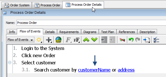
- In the Process Order Details window that opens, select the Flow of Events tab.

-
Click on the first row (in the white space). Type Login to the System. Press ENTER.
Type Click new Order. Press ENTER.
Type Select customer. Press ENTER.
- To further elaborate step 3, we will now indent the fourth row, which will become step 3.1. Click Increase Indent.

- Type Search customer by (leave a space at the end after 'by').

- At the position of the mouse cursor shown above, right-click and select Add Class...

-
A dialog box will open displaying associated classes. Expand to Ordering System > Process Order > Customer. Select name under Customer. Click OK.

Upon clicking OK, the attribute's name will then appear in the flow of events.
- Type ' or ' after the newly added attribute name. Similarly, add another attribute address.

What happens if we change the data structure?
In the Customer class, let's say we want to change the attribute name to customerName. In the class diagram, double-click on name and rename it to customerName.
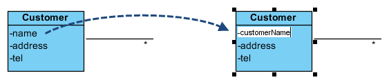
If you return to the flow of events, you will see that the attribute change has already been reflected automatically.